


21
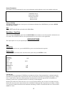
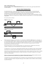
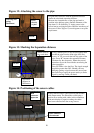
Figure 12: Attaching the sensor to the pipe
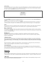
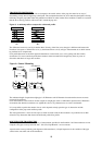
Figure 13: Marking the Separation distance
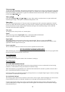
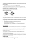
Figure 14: Positioning of the sensor cables
Program the Electronics with the application data to
obtain the calculated separation distance.
Measure the circumference of the pipe and mark a
position at the halfway point. (Outside Diameter of the
pipe times 3.142 divided by 2). Apply grease to the
second sensor and plug the blue connector into the top o
f
the sensor. Follow (figure 13) next diagram to set up the
sep distance.
Using a marker pen or a strip of ticket paper mark
around the pipe from the front edge of the first
sensor “A” till you reach the half way point of the
pipe. From “B” measure the separation distance
calculated by the electronics. Mount the second
transducer as per the first with the stem facing the
other transducer.
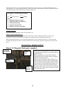
Press ENTER to view the flow. The signal strength
should be greater than 50%. Should you have
difficulty getting a signal remove the sensor from
the Gull wing re-apply the grease and try to find a
signal by moving it with your hand.
Position the Red sensor cable upstream and the Blue
cable Downstream. The Electronics will display a
p
ositive flow reading with cables in this orientation.
If the unit displays a negative reading the cables
have been connected into the wrong sensors.
FLOW
FLOW
Sensor stems to
face each other
Gull wing and
spring
attachment
Peizo
electric
crystal
FLOW
Seperation
distance in
Millimetres
A
B
Red
connector
upstream
Blue connector
downstream