


19
An uneven surface that prevents the transducers from sitting flat on the surface of the pipe can cause Signal Level and
Zero Offset problems. The following procedure is offered as a guide to good practice with respect to positioning and
mounting the transducers.
1) Select the site following the rules laid down on page 19 -
Transducer Positioning.
2) Inspect the surface of the pipe to ensure it is free from rust or is not uneven for any reason. Transducers can be
mounted directly on painted surfaces as long as the surface is smooth and that the underlying metal surface is free from
rust bubbles. On bitumen or rubber coated pipes the coating must be removed in the area under the transducer as it is
preferable that the transducers are mounted directly on to the base metal.
3)
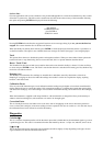
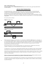
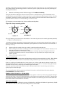
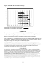
Transducers can be mounted on both Vertical and Horizontal Pipe Runs.
Figure 10:- Sensor mounting position
4)
Apply Interface grease to the face of the transducers. The amount of grease used is extremely important particularly
on pipes of less than 89mm bore.
On Stainless Steel Pipes the amount of couplant applied should never exceed the amount indicated in the Example on
page 3, For large Plastic and Steel Pipes the amount of grease applied is less critical, however do not use more than is
absolutely necessary.
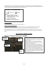
5) Strap the guide rail assembly to the pipe so that it is perfectly parallel to the pipe axis.
6) When screwing the transducers on to the pipe surface use only enough force to ensure that the Transducer is flat
against the pipe surface and then lock in position.
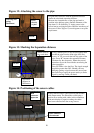
7) Clamping the transducers in exactly the correct position is extremely important. The Separation distance is
calculated by the Portaflow electronics and the transducers must be positioned and clamped exactly at the
distance specified.
8) Always use the sensor grease provided.
LIQUID CONDITIONS
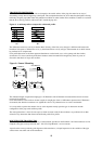
Transit time ultrasonic meters perform best on liquids that are totally free from entrained air and solids. With sufficient
air in the system the ultrasound beam can be attenuated totally and therefore prevent the instrument from working.
Often it is possible to tell whether there is air in the system or not. If a flow signal cannot be obtained a simple test to
determine whether the flow is aerated involves stopping the flow for a period of 10 - 15 minutes. During this time the
air bubbles will rise to the top of the pipe and the flow signal should return.
If the flow signal does return switch on the flow and if sufficient entrained air is locked in the system it will very
quickly disperse and kill the signal.
To correct the Portaflow 216 for operation in the laminar flow region, calculate the Reynolds number adjust the
correction factor
as described on Page 15.
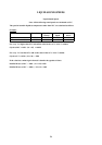
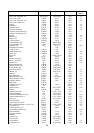
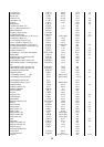
PROPAGATION VELOCITY or SOUND SPEED
To make a flow measurement using the Portaflow 216 on any liquid, it is necessary to know the propagation velocity in
metres/second. There is a short list of fluids that appear on the display when programming (See page 9), showing water
and various other liquids. However if the liquid you wish to measure is not on this list, please revert to the table at the
back of this manual or contact Micronics for advice.
REYNOLDS NUMBER
The Portaflow 216 has been calibrated to operate on Turbulent flows with Reynolds Number of approximately 100,000.
The calibration of the unit will not be valid if the Reynolds No.is below 4000.
TOP
BOTTOM
INCORRECT
TOP
BOTTOM
CORREC
T