


20
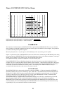
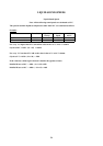
If the Portaflow 216 is to be used on laminar flow applications it will be necessary to calculate the Reynolds No for
each application. To calculate the Reynolds No it is necessary to know the Kinematic viscosity in Centistokes; the flow
velocity and the pipe inside diameter. Please follow the table below
MAXIMUM FLOW
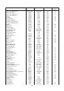
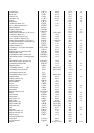
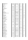
The maximum flow is dependent on the velocity and pipe size.
APPLICATION TEMPERATURE
On any application whose operating temperature is either above or below ambient temperature ensure that the
transducers reach and are maintained at the application temperature before undertaking a measurement.
When applying the transducers to low temperature applications do not allow the pipe surface to ice up between the
transducer and the pipe wall. The ice will force the block away from the pipe wall and consequently you will lose the
signal.
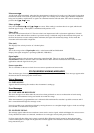
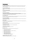
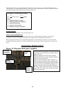
DIAGONAL MODE SETUP
Figure 11: Diagonal Mode parts supplied
To calculate
R
e
use the following formula: -
R
dv
e
=
υ
1
7730()
or
R
dv
e
=
11
1
1000
υ
()
Where
d
= inside pipe diameter in inches
d
1
= inside pipe diameter in millimetres
v
= velocity in feet/second
v
1
= velocity in metres/second
υ
1
= Kinematic viscosity in centistokes
As part of your New Portaflow 216 kit you will fin
d
two stainless steel gull wings, two springs and two
lengths of chain.
Take the transducers from the reflex guiderail.
Attach the Gull-wing to each transducer using the
washer & wing nut provided.
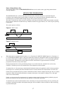
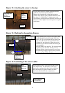
Apply grease to the bottom of the transducer (as
shown on page3). Wrap the chain around the pipe
as shown. Expand the spring and carefully slide the
chain into the slot on the Gull Wing. Plug the red
connector into the socket on the upstream sensor.
The sensor with the red cable must be positioned up
stream. The stem of the sensor must point towards
the downstream sensor.
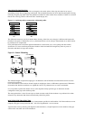
Spring
tensioning
Piezo
electric
cr
y
stal
Sensor
stem
Gull-wing
attachment