


106
Frequency setting by external terminals
4.7.3 Input compensation of multi-speed and remote setting (Pr. 28)
The above parameters can be set when Pr. 160 User group read selection = "0". (Refer to page 201)
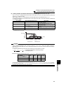
4.7.4 Remote setting function (Pr. 59)
The above parameters can be set when Pr. 160 User group read selection = "0". (Refer to page 201)
* External operation frequency (other than multi-speed) or PU running frequency
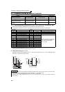
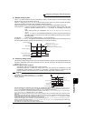
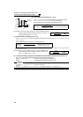
By inputting the frequency setting compensation signal (terminal 1, 2), the speed (frequency) can be compensated
for relative to the multi-speed setting or the speed setting by remote setting function.
Parameter
Number
Name Initial Value Setting Range Description
28
Multi-speed input
compensation selection
0
0 Without compensation
1 With compensation
REMARKS
⋅ Select the compensation input voltage (0 to ±5V, 0 to ±10V) and used terminal (terminal 1, 2) using Pr. 73 Analog input selection.
♦ Parameters referred to ♦
Pr. 4 to Pr. 6, Pr. 24 to Pr. 27, Pr. 232 to Pr. 239 (multi-speed operation) Refer to page 102
Pr. 73 Analog input selection Refer to page 185
Pr. 59 Remote function selection Refer to page 106
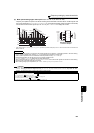
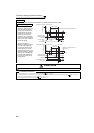
Even if the operation panel is located away from the enclosure, you can use contact signals to perform
continuous variable-speed operation, without using analog signals.
By simply setting this parameter, you can use the acceleration, deceleration and setting clear functions of
the motorized speed setter (FR-FK).
Parameter
Number
Name
Initial
Value
Setting
Range
Description
RH, RM, RL
Signal Function
Frequency Setting
Storage Function
Deceleration to the
Frequency Lower
Than the Set
Frequency
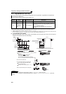
59
Remote function
selection
0
0 Multi-speed setting ⎯⎯
1 Remote setting Used Disabled
2 Remote setting Not used Disabled
3 Remote setting
Not used
(Turning STF/STR
OFF clears remotely-
set frequency.)
Disabled
11 Remote setting Used Enabled
12 Remote setting Not used Enabled
13 Remote setting
Not used
(Turning STF/STR
OFF clears remotely-
set frequency.)
Enabled
Acceleration
Deceleration
Clear
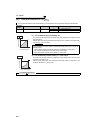
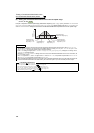
Inverter
STF
RH
RM 10
2
5
RL
Connection
diagram for remote setting
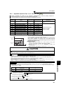
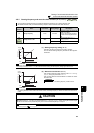
Forward
rotation
SD
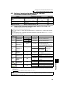
Deceleration
(RM)
Clear (RL)
Acceleration
(RH)
Forward
rotation (STF)
ON
ON
Power supply
ON
0Hz
*
ON
ON
ON
ON
ON
ON
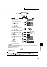
When Pr. 59 = 1, 11
When Pr. 59 = 2, 3, 12, 13
ON
ON
Output frequency
(Hz)
When Pr. 59 = 1, 2, 11, 12
When Pr. 59 = 3, 13
Time