


329
Check first when you have a trouble
5
PROTECTIVE FUNCTIONS
5.5.12 Speed does not accelerate
5.5.13 Unable to write parameter setting
5.5.14 Power lamp is not lit
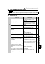
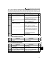
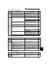
Check
points
Possible Cause Countermeasures
Refer
to
page
Input
signal
Start command and frequency command are chattering.
Check if the start command and the frequency
command are correct.
—
The wiring length used for analog frequency command
is too long, and it is causing a voltage (current) drop.
Perform analog input bias/gain calibration.
193
Input signal lines are affected by external EMI.
Take countermeasures against EMI, such as using
shielded wires for input signal lines.
46
Parameter
Setting
Pr. 1, Pr. 2, Pr. 18, calibration parameter C2 to C7 settings
are improper.
Check the settings of Pr. 1 Maximum frequency and Pr. 2
Minimum frequency. If you want to run the motor at 120Hz
or higher, set Pr. 18 High speed maximum frequency.
96
Check the calibration parameter C2 to C7 settings.
193
During IPM motor control, maximum frequency is limited to
the maximum motor speed (frequency) of the IPM motor.
360
The maximum voltage (current) input value is not set
during the external operation. (Pr.125, Pr.126, Pr.18)
Check the Pr.125 Terminal 2 frequency setting gain
frequency and Pr.126 Terminal 4 frequency setting gain
frequency settings. To operate at 120Hz or higher, set
Pr.18 High speed maximum frequency.
96, 193
Torque boost (Pr. 0, Pr. 46) setting is improper under V/F
control, so the stall prevention function is activated.
Increase/decrease Pr. 0 Torque boost setting value by
0.5% increments so that stall prevention does not occur.
87
V/F pattern is improper when V/F control or Simple
magnetic flux vector control is performed.
(Pr. 3, Pr. 14, Pr. 19)
Set rated frequency of the motor to Pr. 3 Base frequency.
(V/F control, Simple magnetic flux vector control)
Use Pr. 19 Base frequency voltage to set the base voltage
(e.g. rated motor voltage). (V/F control, Simple magnetic
flux vector control)
98
Change Pr. 14 Load pattern selection according to the load
characteristic. (V/F control)
100
Stall prevention function is activated due to a heavy
load.
Reduce the load weight. —
Set Pr. 22 Stall prevention operation level higher according
to the load. (Setting Pr. 22 too large may result in
frequent overcurrent trip (E.OC).)
91
Check the capacities of the inverter and the motor. —
During PID control, output frequency is automatically controlled to make measured value = set point.
261
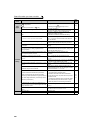
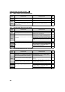
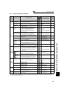
Check
points
Possible Cause Countermeasures
Refer
to
page
Input
signal
Operation is being performed (signal STF or STR is
ON).
Stop the operation.
When Pr. 77 = "0" (initial value), write is enabled only
during a stop.
200
Parameter
Setting
You are attempting to set the parameter in the External
operation mode.
Choose the PU operation mode.
Or, set Pr. 77 = "2" to enable parameter write regardless
of the operation mode.
200
Parameter is disabled by the Pr. 77 Parameter write
selection setting.
Check Pr. 77 Parameter write selection setting.
200
Key lock is activated by the Pr. 161 Frequency setting/key
lock operation selection setting.
Check Pr. 161 Frequency setting/key lock operation selection
setting.
295
Operation mode and a writing device do not
correspond.
Check Pr. 79, Pr. 338, Pr. 339, Pr. 550, Pr. 551, and select
an operation mode suitable for the purpose.
206,
219
Attempted to set "25" in Pr.72 PWM frequency selection
under IPM motor control. Attempted to perform IPM
motor control while Pr.72 ="25."
Pr.72 cannot be set to "25" during the IPM motor control.
(The sine wave filter (MT-BSL/BSC) cannot be used
under IPM motor control.)
183
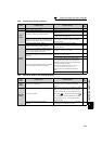
Check
points
Possible Cause Countermeasures
Refer
to
page
Main
Circuit,
Control
Circuit
Wiring or installation is improper.
Check for the wiring and the installation.
Power lamp is lit when power supply is input to the
control circuit (R1/L11, S1/L21).
16