


7
© 2011 Schneider Electric All Rights Reserved.
ZL0093-0A
11/2011
EM3555
Installation
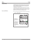
INSTALLATION
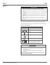
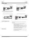
NOTE: Observe correct CT orientation.
The meter can be mounted in two ways: on standard 35 mm DIN rail or
screw-mounted to the interior surface of the enclosure.
A. DIN Rail Mounting
1. Disconnect and lock out power. Use a properly rated voltage sensing device
to confirm power is off.
2. Attach mounting clips to the underside of the housing by sliding them into
the slots from the inside. The stopping pegs must face the housing, and the
outside edge of the clip must be flush with the outside edge of the housing.
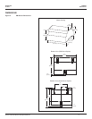
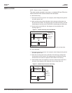
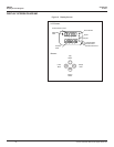
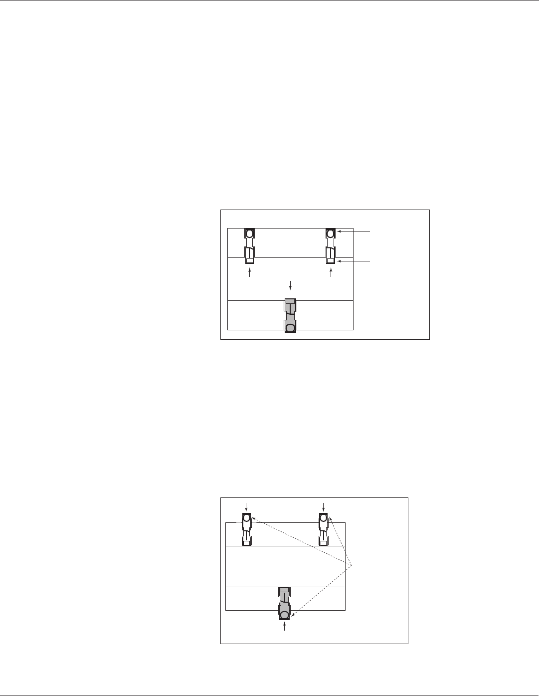
3. Snap the clips onto the DIN rail. See diagram of the underside of the
housing (Figure 3).
Figure 3 Attach mounting clips for DIN Rail
Clip flush
with outside
edge
Snap onto
DIN rail
Insert clips from
inside
4. To prevent horizontal shifting across the DIN rail, use two end stop clips.
B. Screw Mounting
1. Disconnect and lock out power. Use a properly rated voltage sensing device
to confirm power is off.
2. Attach the mounting clips to the underside of the housing by sliding them
into the slots from the outside. The stopping pegs must face the housing,
and the screw hole must be exposed on the outside of the housing.
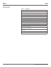
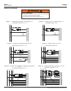
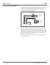
3. Use three #8 screws (not supplied) to mount the meter to the inside of the
enclosure. See diagram of the underside of the housing (Figure 4).
Figure 4 Attach Clips for screw mounting
Screw
holes
exposed
for
mounting
Insert clips from
outside