


32
© 2011 Schneider Electric All Rights Reserved.
EM3555
Modbus Point Map
ZL0093-0A
11/2011
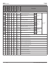
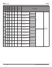
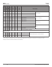
REGISTER
R/W
NV
Format
Units
Scale
Range
Description
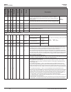
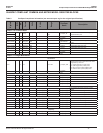
149 R/W NV UInt 1-6
Number of Sub-Intervals per Demand Interval. Sets the number of sub-intervals
that make a single demand interval. For block demand, set this to 1. Default is
1. When sub-interval length register #150 is set to 0 (sync-to-comms mode), this
register is ignored.
Demand
Calculation
150 R/W NV UInt Seconds 0, 10-32767
Sub-Interval Length in seconds. For sync-to-comms, set this to 0 and use the reset
register (129) to externally re-start the sub-interval. This is also the logging interval.
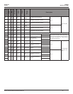
151 R/W UInt 1-32767 Reserved (returns 0)
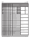
152 R NV UInt 0-32767 Power Up Counter
153 R NV UInt 0-32767
Output Conguration. EM3555 units have a N.O. energy contact and N.C. (Form B) phase loss contact,
so this register will always return a “0”.
154 R UInt Reserved (returns 0)
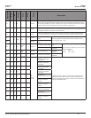
Logging Conguration and Status
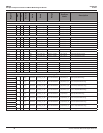
155 R/W NV UInt
Day /
Month
See Bytes
Most Signicant Byte (MSB)
Least Signicant Byte
(LSB)
Date / Time Clock. Following a power cycle, resets
to:
Day 01 Month 01
Hour 00 Year (20) 00
Day 1-31 (0x01-0x1F)
Month 1-12
(0x01-0x0C)
156 R/W NV UInt
Hour /
Year
See Bytes Hour 0-23 (0x00-0x17)
Year 0-199
(0x00-0xC7)
157 R/W NV UInt
Seconds
/
Minutes
See Bytes Seconds 0-59 (0x00-0x3B)
Minutes 0-59
(0x00-0x3B)
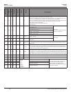
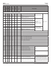
158 R/W NV UInt 0-10
Logging Read Page Register. Selects which of the register logs to read (see registers 169-178). 1-10
are valid entries that put the meter into log reading mode, temporarily pausing logging. When set to 0
(no variable selected for reading), normal logging resumes. The meter will buffer one set of log entries
while in reading mode if a sub-interval timeout occurs (read/write collision). Default is 0.
Note: this buffered data will be written to the log, and logging will resume on the following sub-interval
timeout whether the page register has been cleared or not, resulting in the appearance of data moving
in the buffer during reads. To avoid this, log buffer reads should be completed and this register set back
to 0 in less time than the demand sub-interval (preferred) or logging should be halted by setting Bit 1 in
register 158 (logs may be missed).
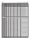
159 R/W NV UInt
Logging Conguration Register (Bit Mapped):
Bit 0: Clear to 0 for circular log buffer mode. Set to 1 for single shot logging mode. Default is 0 (Circular).
Bit 1: Clear to 0 to enable Logging. Set to 1 to halt logging. Default is 0 (Log).
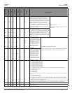
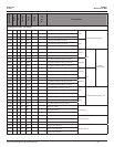
160 R NV UInt
Logging Status Register (Bit Mapped):
Bit 0: Log buffer full – Set to 1 when one single shot mode has lled the log buffer. In this condition,
the Logged Entry Count will continue to increment. Cleared to 0 when logging is restarted (see reset
command register 129).
Bit 1: Log Buffer Read Collision 1 – Set to 1 if the meter tried to save log data while the user was
reading the log (Logging Page Register has been set to something other than 0). On the rst collision,
the meter holds the data until the next sub-interval and then writes the saved data to the log as well as
the data for that interval. This bit is cleared to 0 on the rst demand interval with Logging Page Register
= 0.
Bit 2: Log Buffer Read Collision 2 – Set to 1 on the 2nd attempt to save log data while the user is
reading the log (Logging Page Register is set to something other than 0). At this point the meter ignores
the read condition and does a double write, rst of the values saved from the previous cycle, and then
the present values. If the read condition is not removed the meter continues to write the log data as it
normally would. This bit is cleared to 0 on the rst demand interval with Logging Page Register = 0.
Bit 3: Logging Reset – The log has been reset during the previous demand sub-interval.
Bit 4: Logging Interrupted – logging has been interrupted (power cycled, log conguration change, etc.)
during the previous demand sub-interval.
Bit 5: RTC Changed – The real time clock had been changed during the previous demand sub-interval.
Bit 6: RTC Reset - The real time clock has been reset to the year 2000 and needs to be re-initialized.