


30
© 2011 Schneider Electric All Rights Reserved.
EM3555
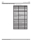
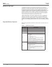
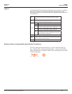
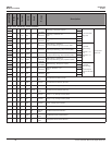
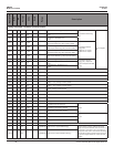
Modbus Point Map
ZL0093-0A
11/2011
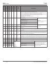
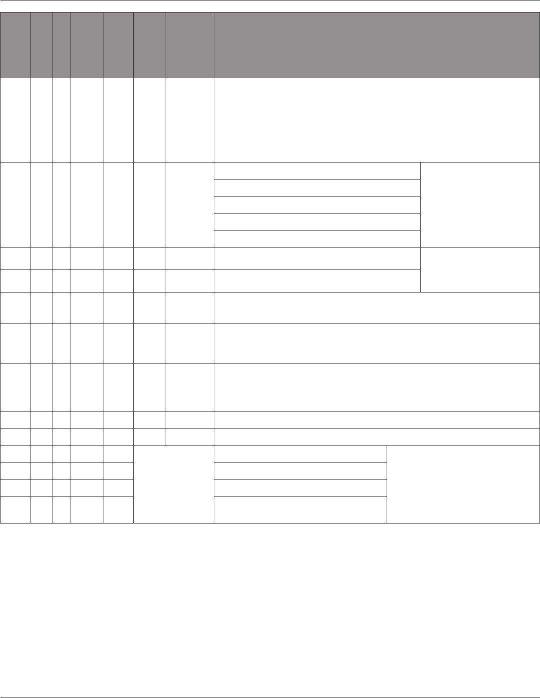
REGISTER
R/W
NV
Format
Units
Scale
Range
Description
129 R/W UInt N/A
Reset:
- Write 30078 (0x757E) to clear all energy accumulators to 0 (all).
- Write 21211 (0x52DB) to begin new demand sub-interval calculation cycle. Takes effect at the end of
the next 1 second calculation cycle. Write no more frequently than every 10 seconds.
- Write 21212 (0x52DC) to reset max. demand values to present demand values. Takes effect at the end
of the next 1 second calculation cycle. Write no more frequently than every 10 seconds.
- Write 16640 (0x4100) to reset logging.
- Write 16498 (0x4072) to clear pulse counts to zero.
- Read (returns 0).
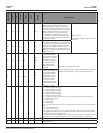
130 R/W NV UInt
10,
11,
12,
31,
40
Single Phase: A + N
System Type
(Note: only the indicated phases are
monitored for phase loss)
Single Phase: A + B
Single Split Phase: A + B + N
3 phase ∆, A + B + C, no N
3 phase Y, A + B + C + N
131 R/W NV UInt Amps 1-32000 CT Ratio – Primary
Current inputs
132 R/W NV UInt 1, 3
CT Ratio – Secondary Interface (1 or 1/3 V, may not be user
congurable)
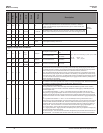
133 R/W NV UInt 100 0.01-320.00
PT Ratio: The meter scales this value by 100 (i.e. entering 200 yields a potential transformer ratio of
2:1). The default is 100 (1.00:1), which is with no PT attached. Set this value before setting the system
voltage (below).
134 R/W NV UInt 82-32000
System Voltage: This voltage is line to line, unless in system type 10 (register 130), which is line to
neutral. The meter uses this value to calculate the full scale power for the pulse conguration (below),
and as full scale for phase loss (register 142). The meter will refuse voltages that are outside the range
of 82-660 volts when divided by the PT Ratio (above).
135 R NV UInt kW W 1-32767
Theoretical Maximum System Power – This read only register is the theoretical maximum power the
meter expects to see on a service. It is calculated by the meter from the system type (register 130), CT
size (register 131), and system voltage (register 134) and is updated whenever the user changes any of
these parameters. It is used to determine the maximum power the pulse outputs can keep up with. This
integer register has the same scale as other integer power registers (see register 140 for power scaling).
136 R UInt Reserved (returns 0)
137 R/W NV UInt 0,1 Display Units: 0 = IEC (U, V, P, Q, S), 1 = IEEE (default: VLL, VLN, W, VAR, VA)
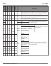
138 R SInt
-4 0.0001
-3 0.001
-2 0.01
-1 0.1
0 1.0
1 10.0
2 100.0
3 1000.0
4 10000.0
Scale Factor I (Current)
Scale Factors
Note: These registers contain a signed integer,
which scales the corresponding integer
registers. Floating point registers are not
scaled. Scaling is recalculated when the meter
conguration is changed.
139 R SInt Scale Factor V (Voltage)
140 R SInt Scale Factor W (Power)
141 R SInt Scale Factor E (Energy)