


19
© 2011 Schneider Electric All Rights Reserved.
ZL0093-0A
11/2011
EM3555
User Interface for Setup
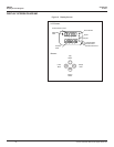
USER INTERFACE FOR SETUP
Next
Next
From:
SETUP > PASWD
ADDR
--------
0
01
BAUD
--------
38400
19200
9600
4800
2400
1200
PAR
--------
nOnE
EvEn
Odd
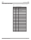
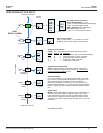
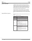
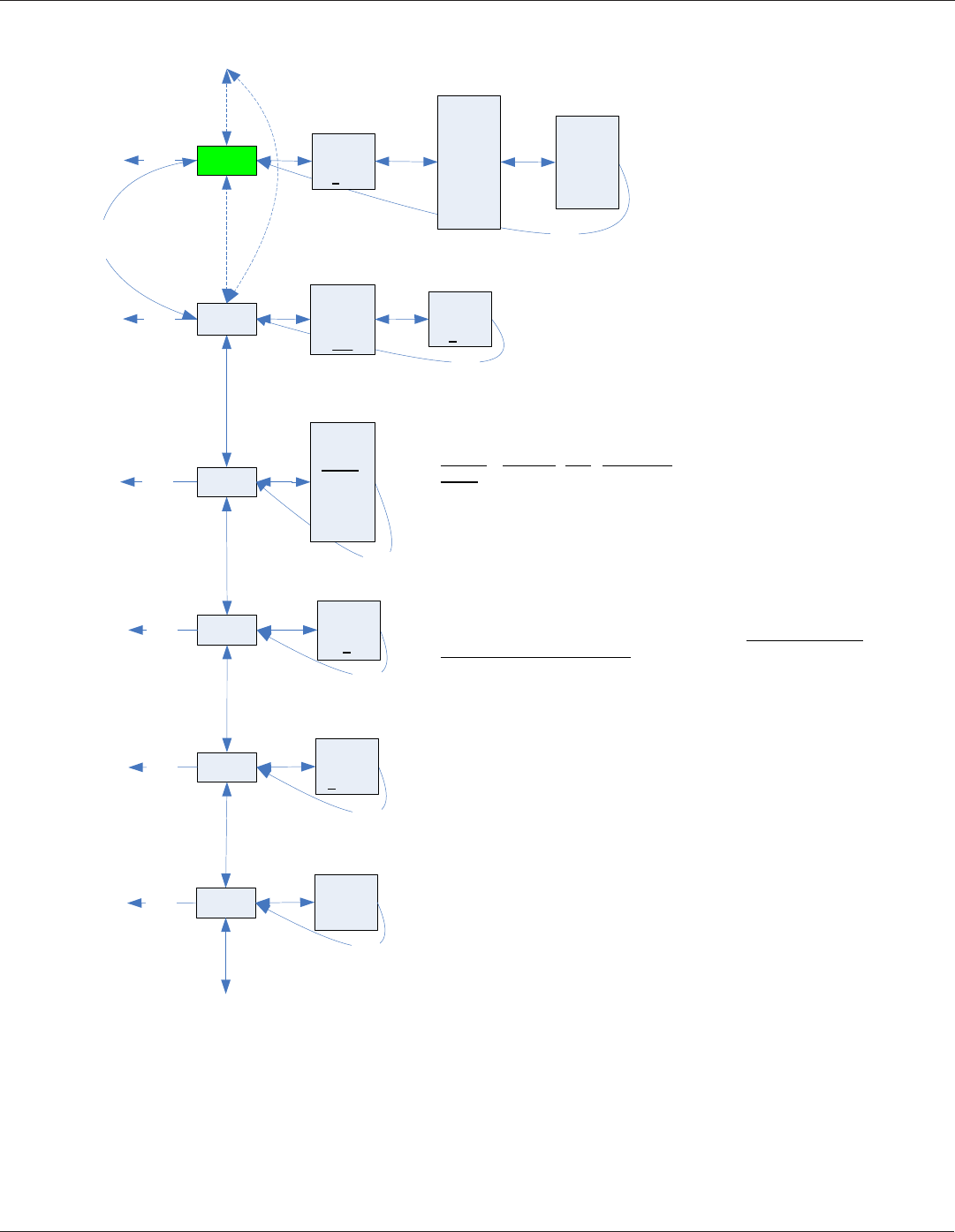
Set Communications Parameters:
ADDR - Modbus Address: 1 – 247.
Press + to increment the selected (blinking) digit.
Press - to select the digit to the left.
BAUD - Baud Rate: 1200 – 38400 Baud
PAR - Parity: Odd, Even, None
Press + or - to step through the options.
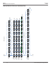
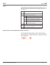
Set Current Transducer:
CT V - CT Input Voltage: + or – to Select 1.0 or 0.33V.
CT SZ - CT Size: in Amps. Maximum is 32000 Amps.
Set System Configuration:
SYSTM: + or – to step through the following System Type options:
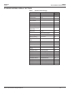
System
Reg 130 CTs Description
3L-1n 40 3 Wye Three Phase: A, B, & C with Neutral (Default).
3L 31 3 Delta Three Phase: A, B & C; no Neutral
2L-1n 12 2 Single Split Phase: A & B with Neutral
2L 11 1 Single Phase: A & B; no Neutral
1L-1n 10 1 Single Phase: A to Neutral
System
Type
Current
Transformer
S SYS
Next
S CT
CT V
--------
1.0
.33
CT SZ
--------
1
00
SYSTM
--------
3L-1n
3L
2L-1n
2L
1L-1n
Back To SETUP
Back
Back
Back S COM
To Setup p. 2 “SPLOS”
Next
S PT
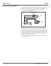
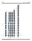
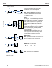
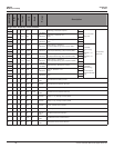
Set Potential Transfomer Ratio:
RATIO – Potential transformer step down is RATIO:1. Default is 1:1
(No PT installed). See Install for wiring diagrams. This value must be
set before the System Voltage (if used).
Potential
Transformer
RATIO
--------
001
.00
Back
S V
Back
Sytem
Voltage
Next
Set System Voltage:
V LL – The nominal Line to Line Voltage for the system. This is used
by the meter to calculate the theoretical maximum system power, and
as the reference voltage for setting the Phase Loss threshold.
Maximum is 32000 Volts. For system type 1+N (10), this is a Line to
Neutral Voltage, indicated by “V LN”. Note: the meter will reject settings
that are not within the meter’s operating range when divided by the PT
ratio.
V LL
--------
0
0600
S PWR
Back
Sytem
Voltage
MX KW
--------
103.92
Next
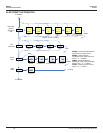
System Power:
MX KW – The theoretical Maximum System Power is calculated by the
meter from the System Voltage, CT size, and System Type. Power
Factor is assumed to be unity. The value of System Power is used to
determine which combinations of pulse weight and duration are valid
and will keep up with the maximum power the meter will see. This value
is read only.
Note: Bold is the Default.
To Setup p. 2 “SPASS”
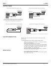
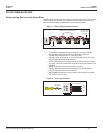
RS-485
Output