


10
© 2011 Schneider Electric All Rights Reserved.
EM3555
Wiring Diagrams
ZL0093-0A
11/2011
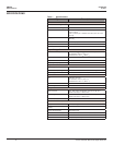
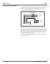
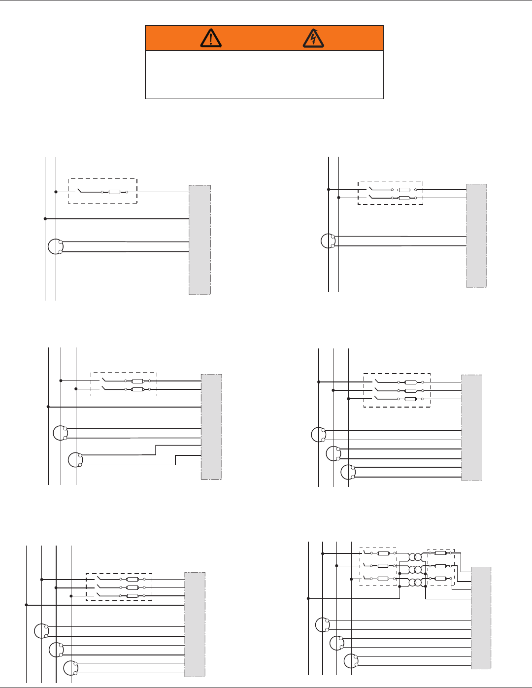
WIRING DIAGRAMS
RISK OF ELECTRIC SHOCK
CT negative terminals are referenced to the meter’s neutral and may be at elevated voltages
· Do not contact meter terminals while the unit is connected
· Do not connect or short other circuits to the CT terminals
Failure to follow these instructions can result in death or serious injury.
WARNING
N L1
X2
X1
White
Black
A
B
C
N
+
-
+
-
+
-
A
B
C
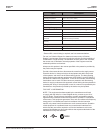
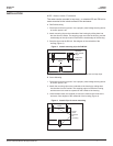
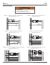
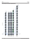
Diagram 1: 1-Phase Line-to-Neutral 2- Wire System 1 CT Diagram 2: 1-Phase Line-to-Line 2-Wire System 1 CT
L1 L2
X2
X1
X2
X1
A
B
C
N
+
-
+
-
+
-
A
B
C
N
White
Black
White
Black
L1 L2
X2
X1
A
B
C
N
+
-
+
-
+
-
A
B
C
White
Black
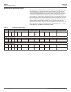
Diagram 3: 1-Phase Direct Voltage Connection 2 CT
L1 L2 L3
X2
X1
A
B
C
N
A
B
C
X2
X1
X2
X1
+
-
+
-
+
-
White
Black
White
Black
White
Black
L1N L2 L3
X2
X1
A
B
C
N
A
B
C
X2
X1
X2
X1
+
-
+
-
+
-
White
Black
White
Black
White
Black
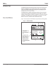
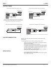
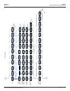
Diagram 4: 3-Phase 3-Wire 3 CT no PT
Diagram 5: 3-Phase 4-Wire Wye Direct Voltage Input Connection
3 CT
Use System Type 11 (2L)
Use System Type 12 (2L + 1n) Use System Type 31 (3L)
Use System Type 40 (3L + 1n)
Use System Type 10 (1L + 1n)
White
Black
White
Black
White
Black
L1N L2 L3
X2
X1
A
B
C
N
A
B
C
X2
X1
X2
X1
+
-
+
-
+
-
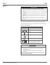
Diagram 6: 3-Phase 4-Wire Wye Connection 3 CT 3 PT
Use System Type 40 (3L + 1n)