


9
© 2011 Schneider Electric All Rights Reserved.
ZL0093-0A
11/2011
EM3555
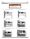
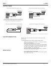
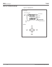
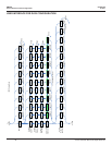
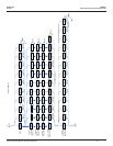
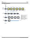
Wiring
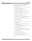
WIRING
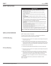
DANGER
HAZARD OF ELECTRIC SHOCK, EXPLOSION, OR ARC FLASH
• Apply appropriate personal protective equipment (PPE) and follow safe
electrical work practices. See NFPA 70E in the USA or applicable local
codes.
• This equipment must only be installed and serviced by qualied electrical
personnel.
• Turn off all power supplying equipment before working on or inside the
equipment.
• Always use a properly rated voltage sensing device to conrm power is
off.
• Read, understand, and follow the instructions before installing this
product.
Failure to follow these instructions will result in death or serious injury.
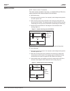
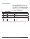
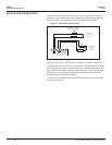
To avoid distortion, use parallel wires for control power and voltage inputs.
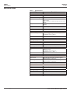
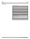
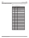
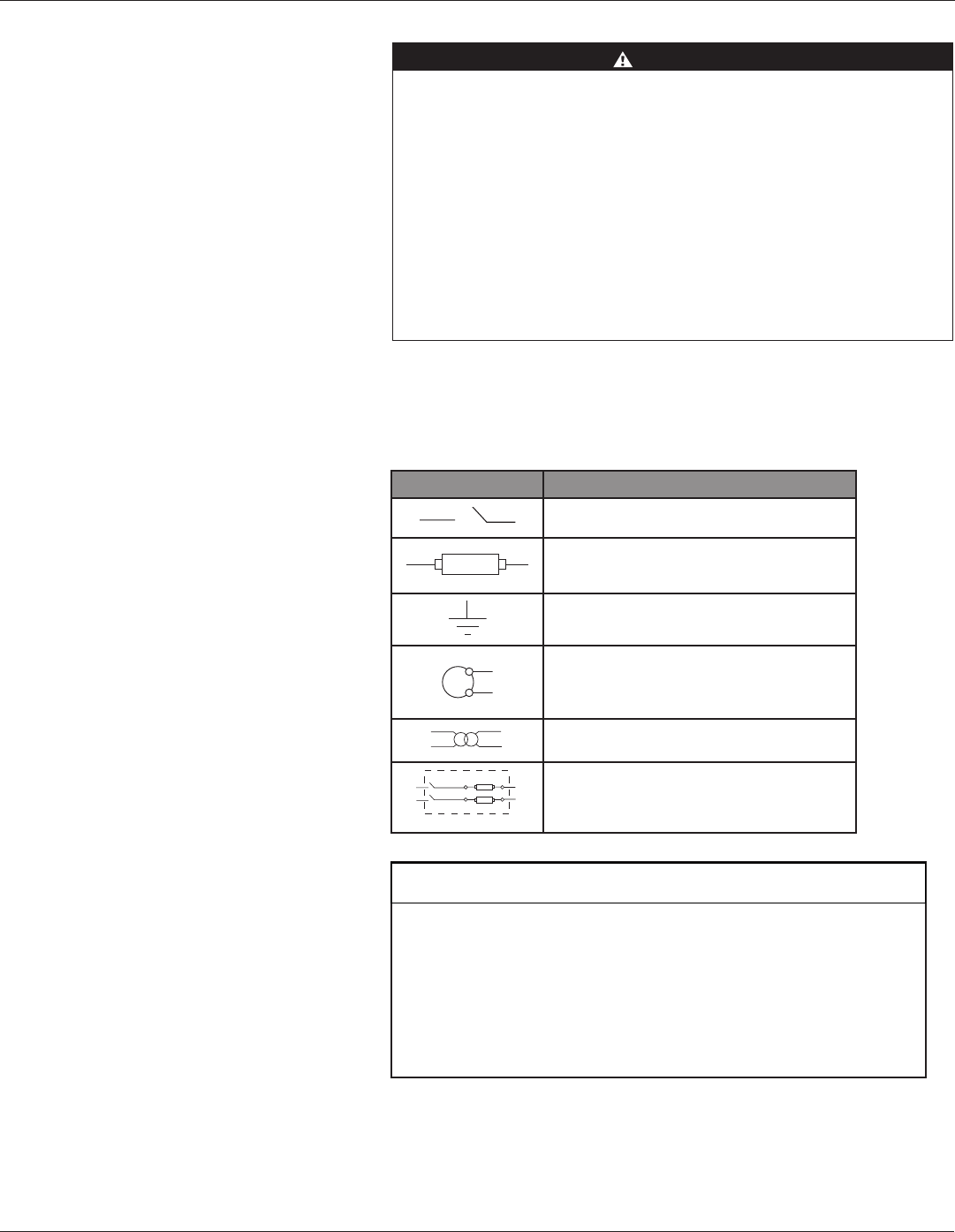
The following symbols are used in the wiring diagrams on the following pages.
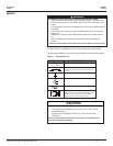
Table 5 Wiring Symbols
Symbol Description
Voltage Disconnect Switch
Fuse (installer is responsible for ensuring compliance
with local requirements. No fuses are included with
the meter.)
Earth ground
S2
S1
Current Transducer
Potential Transformer
Protection device containing a voltage disconnect
switch with a fuse or disconnect circuit breaker. The
protection device must be rated for the available
short-circuit current at the connection point.
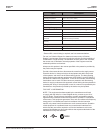
RISK OF EQUIPMENT DAMAGE
• This product is designed only for use with 1V or 0.33V current
transducers (CTs).
• DO NOT USE CURRENT OUTPUT (e.g. 5A) CTs ON THIS
PRODUCT.
Failure to follow these instructions can result in overheating and
permanent equipment damage.
CAUTION