


21
© 2011 Schneider Electric All Rights Reserved.
ZL0093-0A
11/2011
EM3555
RS-485 Communications
RS-485 COMMUNICATIONS
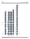
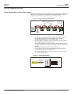
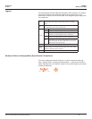
Daisy-chaining Devices to the Power Meter
The RS-485 slave port allows the power meter to be connected in a daisy chain
with up to 63 2-wire devices. In this bulletin, communications link refers to a
chain of devices that are connected by a communications cable.
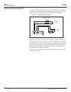
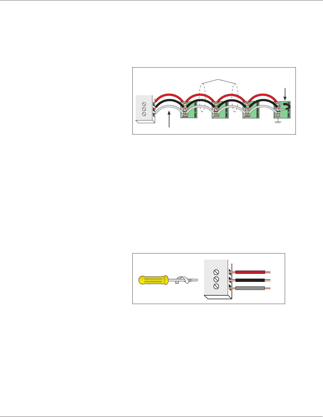
Figure 7 Daisy-chaining multiple devices
–
+
S
Belden 1120 A or equivalent (600 V)
120 Ω terminator
on the rst and
last device of the
daisy chain
Shield wire
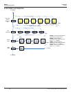
• The terminal’s voltage and current ratings are compliant with the
requirements of the EIA RS-485 communications standard.
• The RS-485 transceivers are ¼ unit load or less.
• RS-485+ has a 47 kΩ pull up to +5V, and RS-485- has a 47 kΩ pull
down to Shield (RS-485 signal ground).
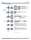
• Wire the RS-485 bus as a daisy chain from device to device, without
any stubs. Use 120 Ω termination resistors at each end of the bus (not
included).
• Shield is not internally connected to Earth Ground.
• Connect Shield to Earth Ground somewhere on the RS-485 bus.
• Use 14-24 gauge wire for all connections.
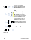
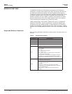
• When tightening terminals, ensure that the correct torque is applied:
3.5 - 4.4 in·lb (0.4-0.5 N·m).
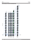
Figure 8 Torque requirements
–
+
S
Red
Black
Gray
3.5–4.4 in•lb
(0.4–0.5 N•m)
Use 14-24 gauge wire