


PowerLogic
TM
Series EM4000 930-134-01-A.00
Installation Guide 11/2013
4 ©2013 Schneider Electric All Rights Reserved
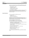
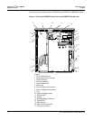
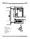
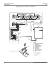
Figure 2 shows the internal view of thePowerLogic EM4033 and EM4080 meters.
Figure 2: PowerLogic EM4033 and PowerLogic EM4080 internal view
1
4
1
6
7
8
10
11
12
13
5
1
1
2
9
15
14
17
16
3
Legend:
1 Cover screw location
2 Meter point input connector
3 Cable connector
4 Mounting keyhole
5 Ingress punch-outs
6 Earth stud
6 Sense voltage terminal block
8 Control voltage terminal block
9 Fuse
10 Control voltage jumper
11 RTU interface
12 Display
13 Remote display connector
14 Serial RS232
15 Ethernet port
16 Pulse in terminal blocks
17 Pulse out connector