


930-134-01-A.00 PowerLogic
TM
Series EM4000
11/2013 Installation Guide
©2013 Schneider Electric All Rights Reserved 21
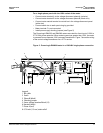
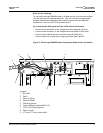
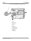
1. Connect the 50-pin connector to the PowerLogic connector located at the
bottom side of the unit, and secure it in place with the retaining clips.
2. Feed the free end of the cable through the bottom left of the meter enclosure.
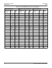
This cable is made up of twisted-pair wires for connecting the individual CTs to the
metered points. The color codes for the X1 (positive) and X2 (neutral) connections for
each CT are listed in Table 2 on page 24.
NOTE: The direction of the energy flow is indicated on the CT.
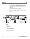
3. Turn off the power feed to the panel where the CTs are being installed. Always
use a properly rated voltage sensing device to confirm power is off.Feed the CT
cable into the panel through an appropriate punch-out with an approved strain
relief.
4. Strip the plastic sheaths on the cable to an appropriate length to expose the wire
pairs. Cut and strip the CT leads and wire pair leads to an appropriate length.
Crimp the CT leads to the wire pairs for each meter point.
5. Connect the X1 lead of the CT to the X1 lead of the cable, then connect the X2
lead of the CT to the X2 lead of the cable (see Table 2).
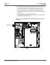
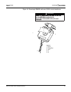
6. When using solid-core CTs, remove the feed wire from the circuit breaker, place
the CT over the wire, and reconnect to the circuit breaker. Ensure that the arrow
on the CT label is pointing in the direction of the energy flow (toward the load).
7. When using split-core CTs, separate the halves of the CT and place the CT over
the wire to the circuit breaker. Ensure that the CT is facing the source as shown
on the label. Install cable ties to ensure that the CT halves are held together
securely.
8. Repeat steps 4 to 7 for the remaining CTs.
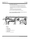
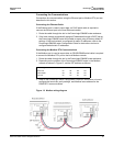
Installing 5A Converters and CTs on the PowerLogic EM4080
When both low-current (200A and 400A) and high-current (600A or higher) circuits
need to be measured with the same PowerLogic meter, converters are available to
allow the use of Measurement Canada approved 5A CTs with the appropriate
current rating. 5A CT converters transform the 5A maximum output from a standard
CT to the 80mA maximum of the PowerLogic meter.
The 5A side of the converter is the black and red wire pair, and the 80mA side of
the converter is the black and white wire pair.
NOTE: It is recommended that 5A converters and shorting devices be installed in a
sealable metal enclosure.
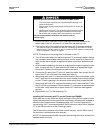
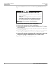
HAZARD OF ELECTRIC SHOCK, EXPLOSION, OR ARC FLASH
• Turn off all power supplying this equipment before working on or
inside the equipment.
• Always use a properly rated voltage sensing device to confirm the
power is off.
• NEVER open circuit a CT; use the shorting block to short circuit the
leads of the CT before removing the connection from the meter.
• Do not crimp the insulation when making the wire connections.
Failure to follow these instructions will result in death or
serious injury.