


PowerLogic
TM
Series EM4000 930-134-01-A.00
Installation Guide 11/2013
18 ©2013 Schneider Electric All Rights Reserved
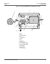
Installing the Current Transformers
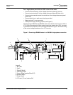
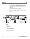
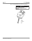
The two models of PowerLogic EM4000 meter use current transformers (CTs) with
different secondary outputs. The PowerLogic EM4033 meter uses split-core 0.333V
CTs (see Figure 10), and the PowerLogic EM4080 meter uses 80mA CTs only (see
Figure 11) and is typically used where accuracy is important and long secondary
CT wiring is required (up to 300 feet [91.44 meters]). The PowerLogic EM4080
meter can also use a 5A CT if a 5A converter has first been installed.
For instructions, see “Installing the CTs on the PowerLogic EM4033 and
PowerLogic EM4080” on page 20, and “Installing 5A Converters and CTs on the
PowerLogic EM4080” on page 21.
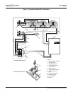
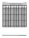
Current transformers connect to the PowerLogic EM4033 and PowerLogic EM4080
meters through the 50-conductor CT cable provided with the meter. Table 2
describes the CT wire pairs and the cable color scheme for each meter point. You
can also find this information on the inside of the meter’s outer cover.
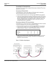
Each CT has an X1 (positive) and X2 (neutral) wire pair and uses butt-splice
connectors to attach the CT to a specific meter wire pair. The direction of the
energy flow is indicated on the CT by: a label (“This side towards source”); an arrow
that points away from the source; or a stamp/label indicating which side is H1 (H1
side faces toward the source).
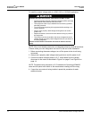
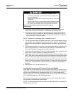
CT shorting blocks are recommended for all CT installations. CTs measuring live
current must either be connected to the PowerLogic meter via the 25-pair CT cable,
or the secondary output of the CTs must be shorted together. Open-circuit CTs
may generate a hazardous voltage and could damage equipment or cause
personal injury.