


930-134-01-A.00 PowerLogic
TM
Series EM4000
11/2013 Installation Guide
©2013 Schneider Electric All Rights Reserved 1
Introduction
This document describes the PowerLogic EM4033 and EM4080 meters, including
procedures to install and start up the unit, and complete the initial configuration:
• “System Description” on page 1
• “Pre-Installation” on page 6
• “Installation Procedures” on page 7
• “Connecting Pulse Inputs” on page 26
• “Fuse Replacement” on page 30
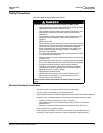
This documentation is intended for those responsible for installing and configuring
the PowerLogic EM4033 and EM4080 meters. Installers must be qualified
electricians with knowledge of local and national code requirements. See “Safety
Precautions” on page 5.
System Description
The PowerLogic EM4033 and EM4080 meters support:
• single-phase, 2-wire
• single-phase, 3-wire (network)
• three-phase wye and Delta services
Depending on how the meters are installed and configured, they can meter 8, 12, or
24 individual meter points. The PowerLogic EM4033 and EM4080 meters are
designed for residential, commercial, and industrial use and display the power and
consumption readings for each measurement point.
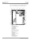
PowerLogic EM4000 series System Specifications
The PowerLogic EM4000 series system architecture includes:
• single-phase, 2-wire; single-phase, 3-wire (network); three-phase, 4-wire (wye);
and three-phase, 3-wire (delta) compatibility
• 2 control voltage variants: 120V 60Hz and 277V 60Hz
• 120/208V, 120/240V and 277/480V configurations, and 347/600V with external
potential transformers
• up to 8, 12, or 24 individual meter points
• local Ethernet configuration interface via PC and web browser
• Ethernet port for remote reporting
• Modbus RTU serial port, for remote reporting
• serial port for remote display
• 2 pulse inputs to connect metering devices
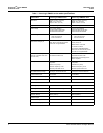
Table 1 lists the system specifications of the PowerLogic EM4033 and EM4080
meters.