


20
6. Configuration
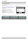
6. 5. Monitored parameters
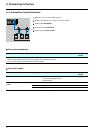
It is possible to select up to 4 parameters to display their values in the [1.2 - MONITORING] menu ([COMMUNICATION MAP] submenu)
on the graphic display terminal.
The selection is made via the [6 – MONITOR CONFIG.] menu ([6.3 - CONFIG. COMM. MAP] submenu).
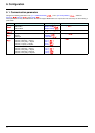
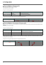
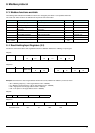
One of the three display formats below can be assigned to each monitored word:
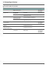
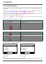
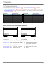
Each parameter [Address 1 select] ... [Address 4 select] can be used to
choose the logic address of the parameter. Select an address of zero
to disable the function.
In the example given here, the monitored words are:
• Parameter 1 = Motor current (LCr): logic address 3204;
signed decimal format
• Parameter 2 = Motor torque (Otr): logic address 3205; signed
decimal format
• Parameter 3 = Last fault occurred (LFt): logic address 7121;
hexadecimal format
• Disabled parameter: address 0; default format: hexadecimal format
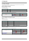
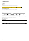
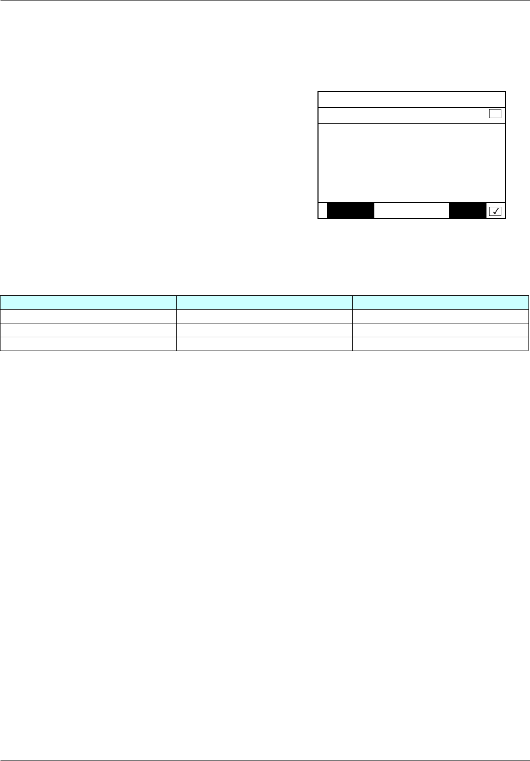
RDY NET +0.00Hz 0A
6.3 CONFIG. COMM. MAP.
Address 1 select : 3204
FORMAT 1 : Signed
Address 2 select : 3205
FORMAT 2 : Signed
Address 3 select : 7121
Code Quick
FORMAT 3 : Hex
Address 4 select : 0
FORMAT 4 : Hex
Format Range Terminal display
Hexadecimal 0000 ... FFFF [Hex]
Signed decimal -32,767 ... 32,767 [Signed]
Unsigned decimal 0 ... 65,535 [Unsigned]