


40
9. Appendix
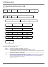
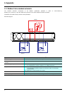
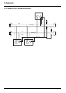
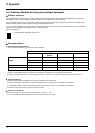
9. 2. Modbus 2-wire standard schematic
The standard schematic corresponds to the Modbus specification published in 2002 on www.modbus.org
(Modbus_over_serial_line_V1.pdf, Nov 2002) and, in particular, to the 2-wire multipoint serial bus schematic.
The Modbus card (VW3 A3 303) conforms to this specification.
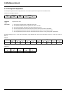
Schematic diagram:
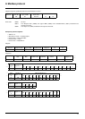
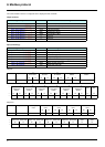
Type of trunk cable
Shielded cable with 1 twisted pair and at least a 3
rd
conductor
Maximum length of bus
1000 m at 19200 bps with the Telemecanique TSX CSAp00 cable
Maximum number of stations (without
repeater)
32 stations, i.e., 31 slaves
Maximum length of tap links
• 20 m for one tap link
• 40 m divided by the number of tap links on a multiple junction box
Bus polarization
• One 450 to 650 Ω pull-up resistor to the 5 V (650 Ω or thereabouts recommended)
• One 450 to 650
Ω pull-down resistor to the Common (650 Ω or thereabouts
recommended)
This polarization is recommended for the master.
Line termination
One 120 Ω 0.25 W resistor in series with a 1nF 10 V capacitor
Common polarity
Yes (Common), connected to the protective ground at one or more points on the bus
1n F
650 Ω
650 Ω
120 Ω
1n F
120 Ω
5 V
0 V
G
R
G
R
G
R
D1
Common
D0
Slave 1
Slave n
Master