


44
9. Appendix
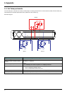
9. 6. Creating a Modbus bus using non-standard equipment
b Different scenarios
M If the Modbus bus is created using the latest-generation Telemecanique devices and Telemecanique Modbus wiring accessories,
installation is simple and no calculation is required (see the section entitled "Connecting to the bus").
M If a new Modbus bus has to be created using devices of different brands or older-generation devices, which do not comply with the
Modbus standard, several checks are required (see "Recommendations" below).
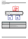
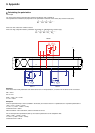
M If, on an existing Modbus bus, a device with 4.7 kΩ polarization is to be replaced by a new-generation device, set the 2 polarization
switches to the lower position to activate the card’s 4.7 kΩ polarization.
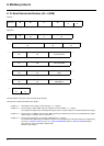
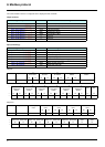
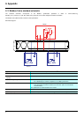
Polarization switches:
4.7 k
Ω RS485 line polarization at drive level
b Recommendations
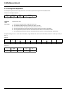
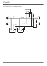
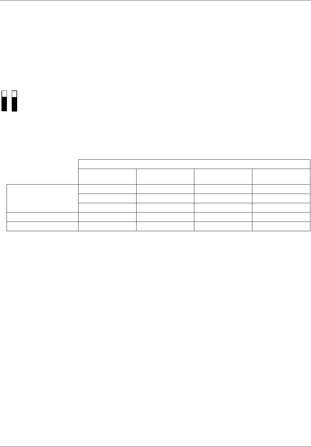
1. Identify the polarities D0 and D1.
They are labeled in different ways depending on the standard:
However, certain RS485 electronic components are labeled in the opposite way to the EIA/TIA-485 standard.
It may be necessary to perform a test by connecting a master to a slave, then reversing the connection in the event of failure.
2. Check polarizations
Check the documentation supplied with the devices to determine their polarization.
If there is a polarization, check that the equivalent polarization value is correct (see "Calculating the polarization").
It is not always possible to implement correct polarization (for example, if the 5 V is not available on the master).
In this case, it may be necessary to limit the number of slaves.
3. Choose a line terminator
If there is a polarization, select an RC line terminator (R = 120 Ω, C = 1 nF)
If it is not possible to install a polarization, select an R line terminator (R = 150 Ω).
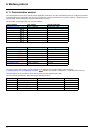
Standard
Modbus EIA/TIA-485
(RS 485)
Uni-Telway Jbus
Signals
D0 A/A’ D (A) RD +/TD + or L +
D1 B/B’ D (B) RD -/TD - or L -
Common C/C’ 0VL
Generator
BG
Receiver
RR