


46
9. Appendix
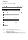
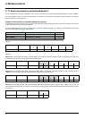
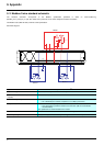
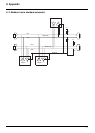
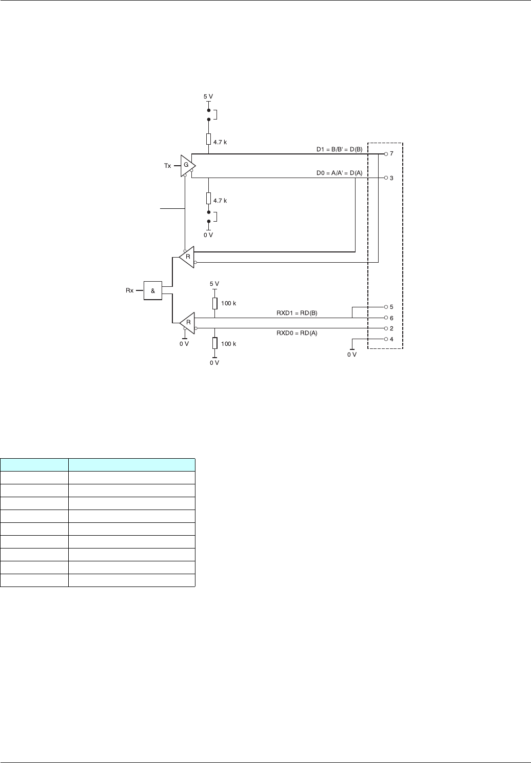
9. 7. RS485 schematic for the card
The RS485 interface on the Modbus card is electrically isolated from the drive.
Schematic diagram:
The polarization switches are used to connect or disconnect the pull-up and pull-down resistors, which implement either Modbus (no slave
polarization) or Uni-Telway (4.7 kΩ polarization for each station) type polarization.
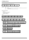
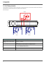
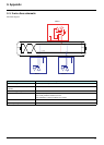
9. 8. Card connector pinout
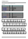
Contact no. Signal
1 Reserved
2RXD0 = RD(A)
3 D0 = A/A’ = D(A)
4 Common = C/C’ = 0VL
5 RxD1 = RD(B)
6 RxD1 = RD(B)
7 D1 = B/B’ = D(B)
8 Not connected
9 Not connected
Ω
Ω
Ω
Ω
Polarization switch
Pull-up polarization resistor
Female 9-way
SUB-D
Pull-down polarization resistor
Polarization switch
Enable