


22
7. Diagnostics
7. 3. Control - Command
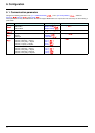
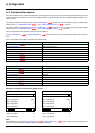
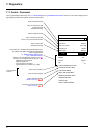
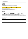
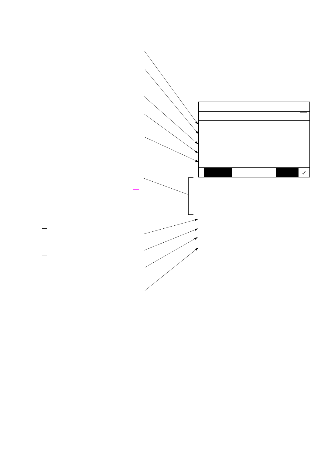
On the graphic display terminal only, the [1.2 - MONITORING] menu ([COMMUNICATION MAP] submenu) can be used to display control-
signal diagnostic information between the drive and the master:
RUN NET +50.00Hz 80A
COMMUNICATION MAP
Command Channel : Com. card
Cmd value : 000F
Hex
Active ref. channel : Com. card
Frequency ref. : 500.0
Hz
Status word : 8627
Hex
Code Quick
W3204 : 53
W3205 : 725
W7132 : 0000
Hex
W0 : -----
Hex
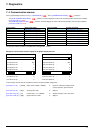
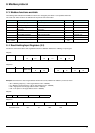
COM. SCANNER INPUT MAP
COM SCAN OUTPUT MAP
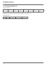
CMD. WORD IMAGE
FREQ. REF. WORD MAP
MODBUS NETWORK DIAG
MODBUS HMI DIAG
CANopen MAP
PROG. CARD SCANNER
Active command channel
Value of control word used
to control the drive
(hexadecimal format)
Active reference channel
Value of frequency reference
(unit 0.1 Hz) used to control the drive
Value of status word
(hexadecimal format)
Values of the four monitored words selected by the user.
The address and display format of these parameters
can be configured in the
[6 - MONITORING CONFIG.] menu,
[6.3 - COM. MAP CONFIG.]
submenu (see "Configuration" section on page 20
).
The value of a monitored word is equal to "-----" if:
- Monitoring is not activated
(address equal to 0)
- The parameter is protected
- The parameter is not known (e.g., 3200)
Value of input variables
Value of output variables
Control word from Modbus
[COM. card cmd.] (CMd3)
Frequency reference from Modbus
[Com. card ref.] (LFr3)
Communication
scanner