


27
8. Modbus protocol
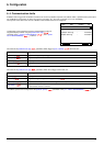
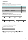
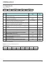
8. 3. Modbus functions available
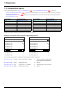
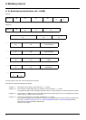
The following table indicates which Modbus functions are managed by the Altivar 71 and specifies their limits.
The "read" and "write" functions are defined from the point of view of the master.
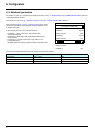
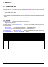
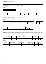
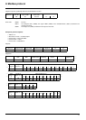
8. 4. Read Holding/Input Registers (3/4)
Functions 3 and 4 access all the drive registers that make no distinction between the "Holding" or "Input" types.
Request:
Response:
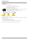
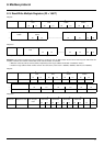
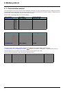
Example: Use function 3 to read 4 logic address words 3102 to 3105 (16#0C1E to 16#0C21) on slave 2, where:
• SFr = Switching frequency = 4 kHz (logic address 3102 = 16#0028)
• tFr = Maximum output frequency = 60 Hz (logic address 3103 = 16#0258)
• HSP = High speed = 50 Hz (logic address 3104 = 16#01F4)
• LSP = Low speed = 0 Hz (logic address 3105 = 16#0000)
Request:
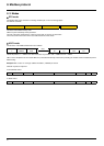
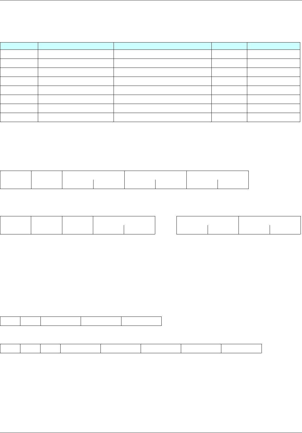
Response:
Code Modbus name Description Broadcast Size of data
3 = 16#03
Read Holding Registers Read N output words
NO
63 words, max.
4 = 16#04
Read Input Registers Read N input words
NO
63 words, max.
6 = 16#06
Write Single Register Write one output word
YES
8 = 16#08
Diagnostics Diagnostics
NO
11 = 16#0B
Get Comm Event Counter Read counter
NO
16 = 16#10
Write Multiple Registers Write N output words
YES
61 words, max.
23 = 16#17
Read/Write Multiple Registers Read/write N words
NO
20/20 words max.
43 = 16#2B
Read Device Identification Identification
NO
Slave no. 03/04 No. of first word Number of words CRC16
Hi Lo Hi Lo Lo Hi
1 byte 1 byte 2 bytes 2 bytes 2 bytes
Slave no. 03/04 Number of
bytes read
First word value ------- Last word value CRC16
Hi Lo Hi Lo Lo Hi
1 byte 1 byte 1 byte 2 bytes 2 bytes 2 bytes
02 03 0C1E 0004 276C
02 03 08 0028 0258 01F4 0000 52B0
Value of: 3102 3103 3104 3105
Parameter code: SFr tFr HSP LSP