36
8. Modbus protocol
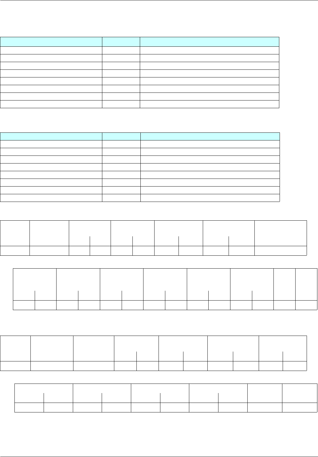
The communication scanner is configured via the display terminal as follows:
Output (control):
Input (monitoring):
Request:
Response:
Configuration parameter Value
Parameter assigned
[Scan. Out1 address] (nCA1) 8501 Control word (CMd)
[Scan. Out2 address] (nCA2) 8602 Speed reference (LFrd)
[Scan. Out3 address] (nCA3) 3104 [High speed] (HSP)
[Scan.Out4 address] (nCA4) 3105 [Low speed] (LSP):
[Scan. Out5 address] (nCA5) 9001 [Acceleration] (ACC)
[Scan. Out6 address] (nCA6) 9002 [Deceleration] (dEC)
[Scan. Out7 address] (nCA7) 0 Not used
[Scan. Out8 address] (nCA8) 0 Not used
Configuration parameter Value Parameter assigned
[Scan. IN1 address] (nNA1) 3201 Status word (EtA)
[Scan. IN2 address] (nNA2) 8604 Output speed (rFrd)
[Scan. IN3 address] (nNA3) 3204 [Motor current] (LCr)
[Scan. IN4 address] (nNA4) 3205 [Output torque] (Otr)
[Scan. IN5 address] (nNA5) 3207 [Power section AC supply voltage] (ULn)
[Scan. IN6 address] (nNA6) 3209 [Drive thermal state] (tHd)
[Scan. IN7 address] (nNA7) 9630 [Motor thermal state] (tHr)
[Scan. IN8 address] (nNA8) 7121 Altivar fault code (LFt)
Slave no. Request code No. of 1
st
word
to be read
No. of words to
be read
No. of 1
st
word to
be written
No. of words to be
written
No. of bytes to be
written
---
Hi Lo Hi Lo Hi Lo Hi Lo ---
14 17 31 C5 00 08 31 D9 00 06 0C ---
--- Value of 1
st
word to be
written
Value of 2
nd
word to be
written
Value of 3
rd
word to be
written
Value of 4
th
word to be
written
Value of 5
th
word to be
written
Value of 6
th
word to be
written
CRC CRC
--- Hi Lo Hi Lo Hi Lo Hi Lo Hi Lo Hi Lo Lo Hi
--- 00 0F 13 88 1F 40 01 F4 04 B0 02 58 56 3D
Slave no. Response code No. of bytes
read
Value of 1
st
word
read
Value of 2
nd
word
read
Value of 3
rd
word
read
Value of 4
th
word
read
---
Hi Lo Hi Lo Hi Lo Hi Lo ---
14 17 10 00 07 13 88 00 64 00 45 ---
--- Value of 5
th
word read Value of 6
th
word read Value of 7
th
word read Value of 8
th
word read CRC CRC
---HiLoHiLoHiLoHiLo Lo Hi
---00F0006500320000 E4 90


