


Chapter 3: System Interface
3-1
Chapter 3
System Interface
3-1 Overview
There are several LEDs on the control panel as well as others on the hard drive
carriers to keep you constantly informed of the overall status of the system as well
as the activity and health of specifi c components. There are also two buttons on
the chassis control panel and an on/off switch on the power supply. This chapter
explains the meanings of all LED indicators and the appropriate response you may
need to take.
3-2 Control Panel Buttons
There are three push-buttons located on the front of the chassis. These are (in order
from left to right) A UID button, a reset button and a power on/off button.
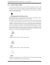
UID
Depressing the UID (unit identifi er) button illuminates an LED on both the front and
rear of the chassis for easy system location in large stack confi gurations. The LED
will remain on until the button is pushed a second time. Another UID button on the
rear of the chassis serves the same function.
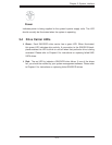
Reset
The reset button reboots the system.
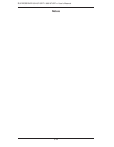
Power
The main power switch is used to apply or remove power from the power supply
to the server system. Turning off system power with this button removes the main
power but keeps standby power supplied to the system.