


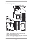

Chapter 5: Advanced Serverboard Setup
5-17
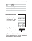
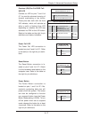
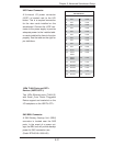
Overheat (OH)/Fan Fail/PWR Fail/
UID LED
Connect an LED to pins 7 and 8 of
JF1 to provide advanced warning of
chassis overheating or fan failure.
These pins also work with the front
UID indicator, which will activate as
either a solid or fl ashing blue LED
depending on whether the LED was
activated via IPMI or the UID button.
Refer to the tables on the right for pin
defi nitions and status indicators.
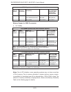
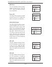
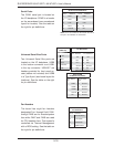
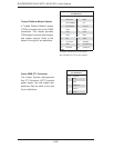
Reset Button
The Reset Button connection is lo-
cated on pins 3 and 4 of JF1. Attach
it to the hardware reset switch on the
computer case. Refer to the table on
the right for pin defi nitions.
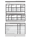
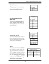
Power Button
The Power Button connection is
located on pins 1 and 2 of JF1. Mo-
mentarily contacting both pins will
power on/off the system. This button
can also be confi gured to function
as a suspend button (see the Power
Button Mode setting in BIOS). To turn
off the power when set to suspend
mode, depress the button for at least
4 seconds. Refer to the table on the
right for pin defi nitions.
Reset Button
Pin Defi nitions (JF1)
Pin# Defi nition
3 Reset
4 Ground
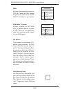
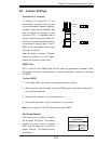
Power Fail LED
Pin Defi nitions (JF1)
Pin# Defi nition
5 Vcc
6 Ground
Power Button
Pin Defi nitions (JF1)
Pin# Defi nition
1 PW_ON
2 Ground
Power Fail LED
The Power Fail LED connection is
located on pins 5 and 6 of JF1. Refer
to the table on the right for pin defi ni-
tions.
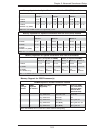
OH/Fan Fail/ PWR Fail/Blue_UID
LED Pin Defi nitions (JF1)
Pin# Defi nition
7 Blue_LED Cathode (UID)
8 OH/Fan Fail/PWR Fail/UID LED
OH/Fan Fail/PWR Fail LED Status
Pin 7 Pin 8 Red LED Blue LED
Low High On: OH/FF/Pwr Fail
(Solid On: OH
Fast Blinking: Fan Fail
Slow Blinking: Pwr Fail)
Off
High Low Off (System normal) On
UID LED
High High Off Off