


Chapter 5: Advanced Serverboard Setup
5-7
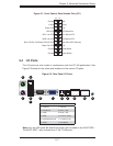
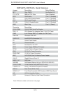
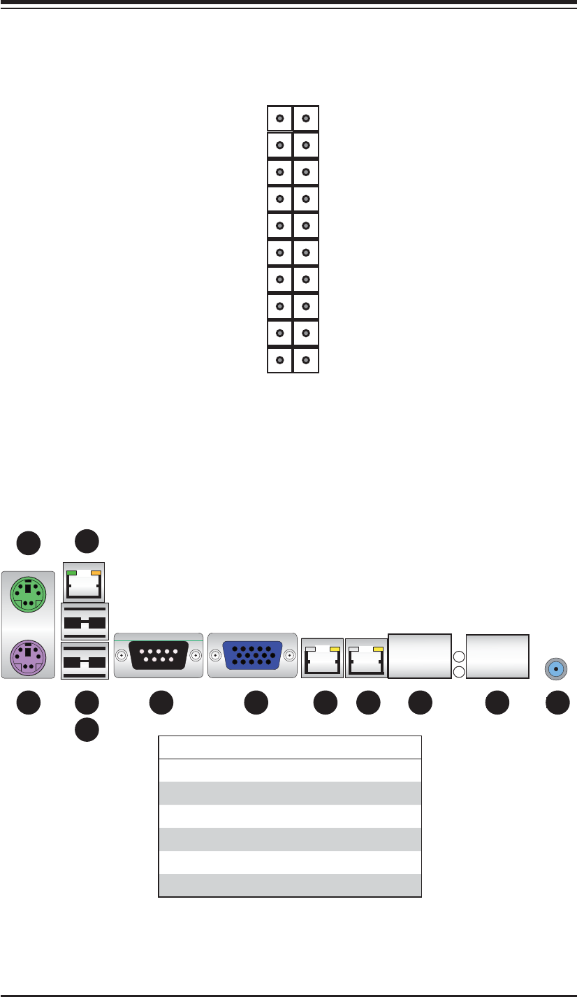
Figure 5-1. Front Control Panel Header Pins (JF1)
NMI
x (key)
3.3V
UID Switch/Vcc
NIC1 Active LED
NIC2 Active LED
Red: (Blue LED Cathode)
3.3V
Reset Button
Power Button
Ground
x (key)
Power LED
HDD LED
NIC1 Link LED
NIC2 Link LED
Blue: OH/Fan Fail/Power Fail/UID LED
Power Fail LED
Ground
Ground
2 1
20 19
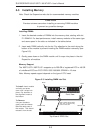
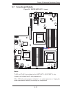
5-4 I/O Ports
The I/O ports are color coded in conformance with the PC 99 specifi cation. See
Figure 5-2 below for the colors and locations of the various I/O ports.
Figure 5-2. Rear Panel I/O Ports
1
2
3
4
5
6 7 8 9 10 11 12
Rear I/O Ports
1. Keyboard 7. VGA Port
2. PS/2 Mouse 8. LAN1 (1 Gb)
3. USB0 9. LAN2 (1 Gb)
4. USB1 10. T-LAN1 (10 Gb)
5. Dedicated IPMI LAN 11. T-LAN2 (10 Gb)
6. COM1 12. UID Button
Note: only two LAN ports (#8 and #9 as shown) are included on the 6016T-6RF+.
The 6016T-6RFT+ also includes the 10 Gb T-LAN ports.