


5-16
SUPERSERVER 6016T-6RFT+/6016T-6RF+ User's Manual
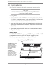
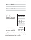
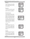
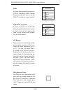
NIC1 LED
The NIC1 (Network Interface Control-
ler) LED connection is located on pins
11 and 12 of JF1. Attach the NIC1
LED cable to display network activity.
Refer to the table on the right for pin
defi nitions.
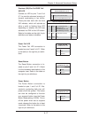
NIC2 LED
The NIC2 (Network Interface Control-
ler) LED connection is located on
pins 9 and 10 of JF1. Attach the NIC2
LED cable to display network activity.
Refer to the table on the right for pin
defi nitions.
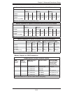
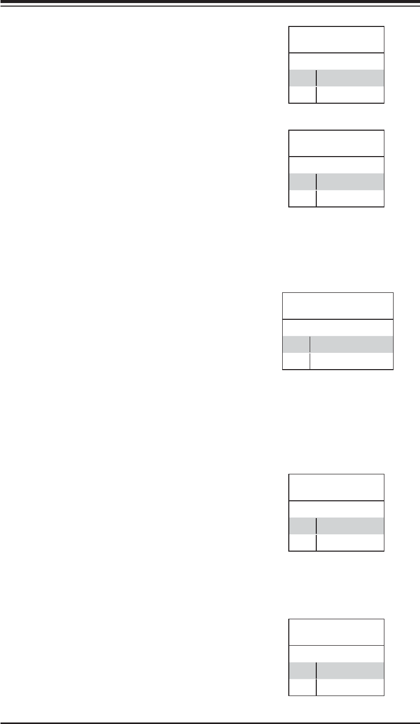
NIC1 LED
Pin Defi nitions (JF1)
Pin# Defi nition
11 Vcc
12 Ground
NIC2 LED
Pin Defi nitions (JF1)
Pin# Defi nition
9 Vcc
10 Ground
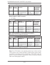
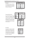
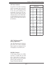
HDD LED/UID Switch
The HDD LED/UID switch connec-
tions are located on pins 13/14 of JF1.
Attach an LED cable to display HDD
activity. This connection can also be
used as a front panel UID (Unit Identi-
fi er) switch. The UID LED on pin 7 of
JF1 works in conjunction with this UID
switch. When the user presses and
releases the UID switch, the UID LED
will be turned on or off to indicate the
location of the unit.
HDD/UID Switch
Pin Defi nitions (JF1)
Pin# Defi nition
13 UID Signal/3.3V SB
14 HD Active
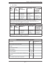
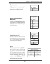
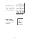
Power LED
The Power LED connection is located
on pins 15 and 16 of JF1. Refer to the
table on the right for pin defi nitions.
NMI Button
The non-maskable interrupt button
header is located on pins 19 and 20
of JF1. Refer to the table on the right
for pin defi nitions.
NMI Button
Pin Defi nitions (JF1)
Pin# Defi nition
19 Control
20 Ground
Power LED
Pin Defi nitions (JF1)
Pin# Defi nition
15 Vcc
16 Control