


Chapter 5: Advanced Serverboard Setup
5-19
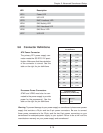
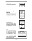
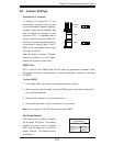
Chassis Intrusion
A Chassis Intrusion header is located
at JL1. Attach the appropriate cable to
inform you of a chassis intrusion.
Chassis Intrusion
Pin Defi nitions
Pin# Defi nition
1 Intrusion Input
2 Ground
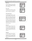
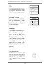
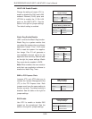
ATX PS/2 Keyboard and PS/2
Mouse Ports
The ATX PS/2 keyboard and the PS/2
mouse ports are located beside the
USB ports. See the table on the right
for pin defi nitions.
PS/2 Keyboard and
Mouse Ports
Pin Defi nitions
Pin# Defi nition
1 Data
2NC
3 Ground
4 VCC
5 Clock
6NC
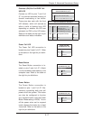
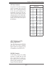
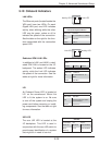
Overheat/Fan Fail LED
Connect an LED to the JOH1 header to
provide warning of a chassis overheat-
ing or fan fail condition. See the table
on the right for pin defi nitions.
Overheat/Fan Fail LED
Pin Defi nitions
Pin# Defi nition
1 +5V
2 Active
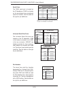
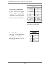
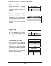
SGPIO
The two headers labeled T-SGPIO-1
and T-SGPIO-2 are for SGPIO (Se-
rial General Purpose Input/Output).
SGPIO supports serial link interfaces
for onboard SATA and SAS ports. Con-
nect the appropriate cables from the
backplane to the SGPIO1 and SGPIO2
headers to utilize SATA/SAS manage-
ment functions on your system.
SGPIO Pin Defi nitions
Pin# Defi nition Pin # Defi nition
1NC 2NC
3 Ground 4 Data
5 Load 6 Ground
7NC 8NC
Note: NC indicates no connection.
OH/Fan Fail LED
Status
State Message
Solid Overheat
Blinking Fan Fail