


5-20
SUPERSERVER 6016T-6RFT+/6016T-6RF+ User's Manual
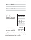
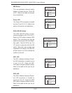
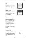
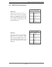
LAN (Ethernet) Ports
Two Ethernet ports (designated LAN1
and LAN2) are located beside the VGA
port on the I/O backplane. A dedicated
IPMI LAN port is also located above
USB1. These ports accept RJ45 type
cables.
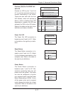
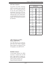
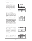
UID Buttons
There are two Unit Identifi cation (UID)
buttons on the serverboard. The Front
Panel UID Switch connects to pin 13
of JF1. The Rear UID Switch (SW1)
is located next to the last LAN port.
Pushing the UID switch on the Front
Control Panel will illuminate both the
Rear UID and the Control Panel UID
indicators. Push the either switch
again to turn off both indicators. These
UID indicators provide easy identifi ca-
tion of a system that may be in need
of service.
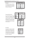
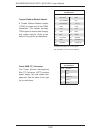
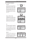
DOM Power Connector
A power connector for SATA DOM
(Disk_On_Module) Devices is located
at JWF1. Connect the appropriate
cable here to provide power support
for your DOM devices.
DOM PWR
Pin Defi nitions
Pin# Defi nition
1 +5V
2 Ground
3 Ground
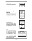
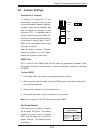
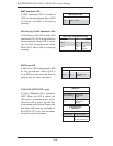
IPMB
A System Management Bus header for
IPMI 2.0 is located at IPMB. Connect
the appropriate cable here to use the
IPMB I
2
C connection on your system.
IPMB
Pin Defi nitions
Pin# Defi nition
1 Data
2 Ground
3 Clock
4 No Connection