


Chapter 5: Advanced Serverboard Setup
5-15
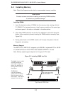
5-8 Connector Defi nitions
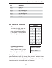
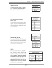
ATX Power Connector
The primary ATX power supply con-
nector meets the SSI EPS 12V speci-
fi cation. Make sure that the orientation
of the connector is correct. See the
table on the right for pin defi nitions.
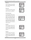
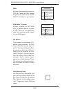
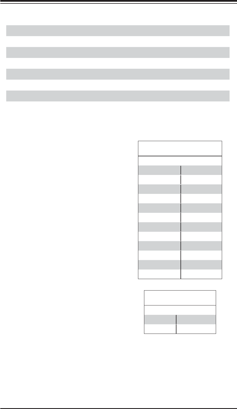
Processor Power
Pin Defi nitions (JPW2/JPW3)
Pins Defi nition
1 through 4 Ground
5 through 8 +12V
Processor Power Connectors
JPW2 and JPW3 must also be con-
nected to the power supply to provide
power for the processor(s). See the
table on the right for pin defi nitions.
Warning: To prevent damage to your power supply or serverboard, please use a power
supply that contains a 24-pin and two 8-pin power connectors. Be sure to connect
these power connectors to the 20-pin and the two 8-pin power connectors on your
serverboard for adequate power supply to your system. Failure to do so will void the
manufacturer warranty on your power supply and serverboard.
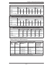
ATX Power 24-pin Connector
Pin Defi nitions
Pin# Defi nition Pin # Defi nition
13 +3.3V 1 +3.3V
14 -12V 2 +3.3V
15 COM 3 COM
16 PS_ON 4 +5V
17 COM 5 COM
18 COM 6 +5V
19 COM 7 COM
20 Res (NC) 8 PWR_OK
21 +5V 9 5VSB
22 +5V 10 +12V
23 +5V 11 +12V
24 COM 12 +3.3V
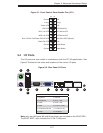
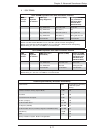
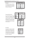
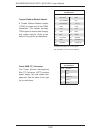
LED Description
LED1 Power LED
LED2 UID LED
LED3 BMC Heartbeat LED
LED4 SAS Activity LED
LED5 SAS Heartbeat LED
LED6 SAS Error LED
LED7 UID LED