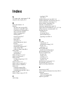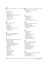
Index
IX–2 975-0055-01-01
)
fan
cooling system
A–3
Fault light
described
1–4
illustrated 1–4, 3–2
fax number for Customer Service WA–1
front panel features
described
1–4, 3–2
illustrated 1–4, 3–2
fuse type 2–9
*
gases, explosive 2–8, B–7
GFCI
protection
1–3
resetting 3–7
GFCI outlets 1–2
connecting appliances to 2–18
described 1–4
illustrated 1–4, 3–2
+
hardwire, AC output connections 2–19
high voltage shutdown 1–3
hydrometer B–8
,
Information about Your System form WA–4
installation codes 2–3
installation procedures
choosing a location
2–7
connecting the chassis ground 2–11
connecting the DC cables 2–16
mounting inverter 2–10
testing 2–22
invert mode
operating in
3–3
inverter
purchase date
WA–4
serial number WA–4
Inverter ON light
described
1–4
illuminated 2–22
illustrated 1–4, 3–2
.
knockout for AC (output) hardwiring
illustrated
1–5
removing 2–19
/
location, choosing 2–7
Low Battery light
described
1–4
illustrated 1–4, 3–2
low battery voltage shutdown 1–3, 3–5
0
materials, AC output hardwiring 2–5
materials, list of 2–4
mounting requirements
S400 Remote Switch
2–12
TS400 2–10
2
On/Standby switch
described
1–4
illustrated 1–4, 3–2
optional remote switch 1–6
turning on 2–22
overload protection 1–3
overload, resetting after 3–7
over-temperature shutdown 1–3
3
polarity of DC connections 2–17
polarity, avoiding reverse 2–16
power output 1–2
power tools 1–2
preparing for installation 2–3
proof of purchase WA–4
protection features 1–3
purchase date WA–4
5
recreational vehicles, chassis grounding 2–11
regulatory approvals A–3
reserve capacity B–3
reverse polarity, caution 2–16


