


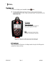
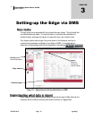
Docking station functionality
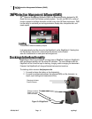
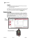
Docking station components
053-644, Rev E Page 12 eg4 & eg3
12
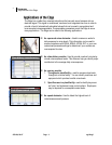
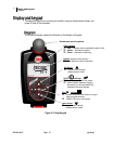
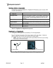
The table below explains the EdgeDock1 or EdgeDock5 LED indicators, power connector, USB
connector, and contact pins.
Table 2-2: EdgeDock1 and EdgeDock5 components
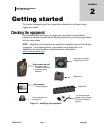
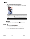
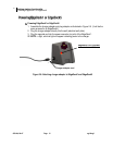
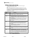
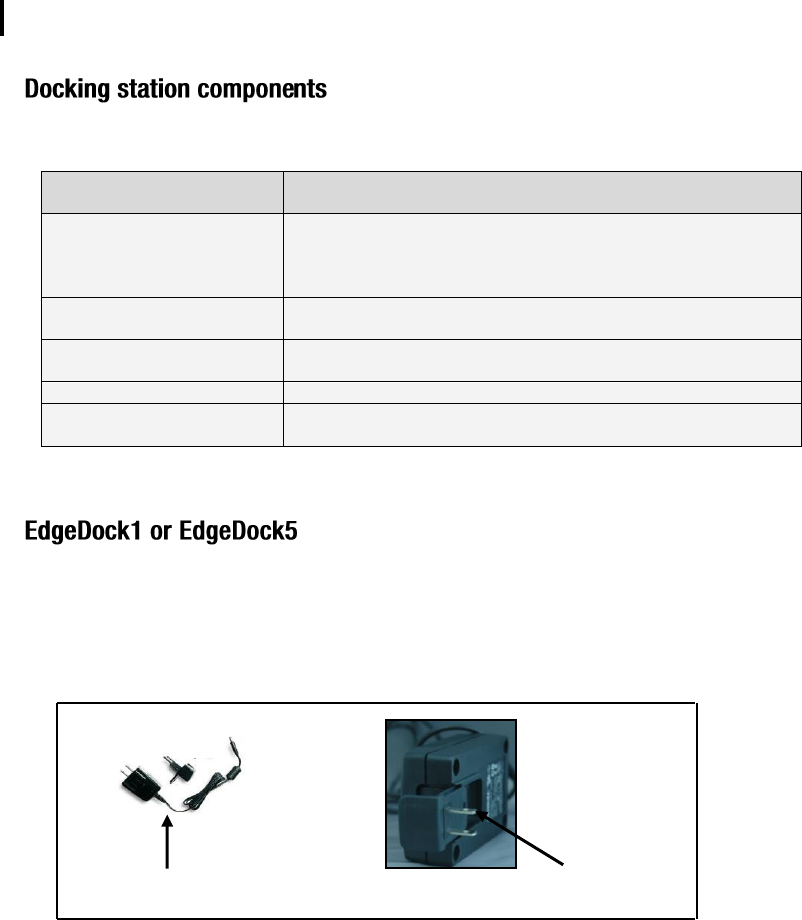
The EdgeDock1 and EdgeDock5 are powered by a 12-volt charger adapter.
Figure 2-5 illustrates the assembly of the charger adapter and the plug adapter. It slides into
place by guiding it down the back cavity (opening) of the power supply.
NOTE: the example is a typical adapter which may be different than the one you are using.
Mechanically, it will function similarly.
Figure 2-5: Attaching the charger adapter with the plug adapter
Docking station
components
Explanation
Charging indicator
Identifies if the dosimeter is “charging” or “fully charged”. A red blinking LED
indicates the dosimeter is charging. A solid green LED equates to a fully
charged dosimeter. (Note the charging indicator is the first, or top, LED
indicator.)
Power indicator
A red LED indicates the docking station is powered on.
Power connector
Attach the power connector cable to the docking station in order to charge
the dosimeter(s).
USB connector
Attach the USB connector to communicate with the dosimeter(s).
Charge Contacts
Placing the dosimeter (s) onto the charge contacts allows charging and
communication.
B. Slide plug adapter into the crevices of base
A. Charger adapter