


Dosimetry
Noise dosimeter
053-644, Rev E Page 2 eg4 & eg3
2
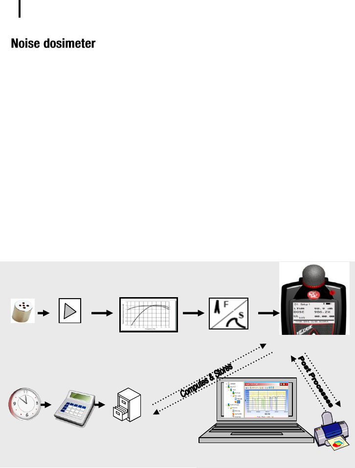
What is a noise dosimeter and how does it compute measurements?
Essentially, a noise dosimeter is composed of the following: a microphone with a
preamplifier, a weighted network, fast or slow response time, an internal clock, calculator,
and memory to store logged data.
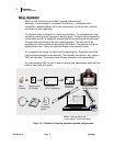
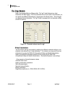
The illustration below is a diagram of a basic noise dosimeter. The microphone will, when
exposed to a sound pressure, generate an electrical signal. The signal will be increased by
a preamplifier, and then is regulated to an applicable level by the range control (dB range).
The signal then goes through a filter set or weighting system. The next circuit is the
response circuit, which controls the dampening of the readout. The response choices are
typically Slow or Fast. Finally, the results will display on the dosimeter screen.
For computation and storage, the clock tracks the sampling time. Dosimeters record how
long sound levels exceeded a set upper limit. The calculator computes an L-avg, a dose, a
TWA, and other data. The memory stores all times, calculations, and measurements.
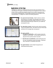
For post-processing, QSP-II is used to view and analyze your measurement results with the
option to view and/or print reports.
Figure 1-2: Illustration of how the dosimeter operates and processes
Mic &
Preamp
Range control
(70-140dB)
Apply filters
(A or C weighting)
A
C
Measurement
results on the Edge
Fast/Slow
Response
File storage
system
Calculator
Clock
QSPII – Manage setup and
create graphs, charts and reports