


iv Table of Contents
Sound Examiner SE-400 Series
Calibration ............................................................................................................................................................................................................... 39
Warranty ................................................................................................................................................................................................................... 39
Data Addendum: SE-400 Series measuring to IEC 61672-1 .............................................................................................................................. 40
Figures:
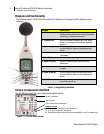
Figure 1-1: SE-400 Screen components ................................................................................................................................................................... 2
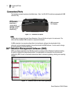
Figure 1-2: Connector and ports ................................................................................................................................................................................ 3
Figure 1-3: Acoustic data and DMS charting example ............................................................................................................................................. 3
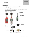
Figure 2-1: Identify SE-400 Series equipment........................................................................................................................................................... 4
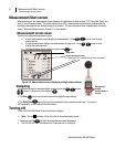
Figure 2-2: Measurement screen ................................................................................................................................................................................ 6
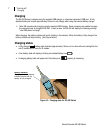
Figure 2-3: Charging state ......................................................................................................................................................................................... 7
Figure 3-1: Response time and frequency weighting ................................................................................................................................................ 8
Figure 3-2: Opening the Setup screen....................................................................................................................................................................... 9
Figure 3-3: Choosing meter settings ........................................................................................................................................................................ 10
Figure 3-4: Choosing meter settings ........................................................................................................................................................................ 10
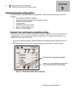
Figure 3-5: Unit Information screen ......................................................................................................................................................................... 11
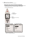
Figure 3-6: Time and Date Setup screen ................................................................................................................................................................ 12
Figure 3-7: Auto-Run screen.................................................................................................................................................................................... 13
Figure 3-8: Auto-Run screen.................................................................................................................................................................................... 13
Figure 3-9: Secure run and measurement screen ................................................................................................................................................... 14
Figure 3-10: Deleting sessions/files and viewing memory ...................................................................................................................................... 15
Figure 4-1: SE-400 Series and calibrating ............................................................................................................................................................... 17
Figure 4-2: Calibration softkey selection ................................................................................................................................................................. 17
Figure 4-3: Calibration screen.................................................................................................................................................................................. 18
Figure 4-4: CAL screen ............................................................................................................................................................................................ 18
Figure 4-5: Example of logged data in DMS ............................................................................................................................................................ 19
Figure 4-6: SE-400 Series with windscreen ............................................................................................................................................................ 19
Figure 4-7: Measurement positioning and tripod mount .......................................................................................................................................... 20
Figure 4-8: Main/multi- measurement screen in Run mode .................................................................................................................................... 21
Figure 4-9: Single measurement screen in stop mode ............................................................................................................................................ 21
Figure 4-10: Session directory screen ..................................................................................................................................................................... 22
Figure 4-11: Saved sessions ................................................................................................................................................................................... 22
Figure 4-12: Reviewing Session Data ..................................................................................................................................................................... 23
Figure 4-13: Sample Sound Examiner data report .................................................................................................................................................. 23
Figure 4-14: Downloading files from DMS to SE-400 Series .................................................................................................................................. 24
Figure 4-15: Baud rate setup and print icon ............................................................................................................................................................ 25
Figure 4-16: Print Setup screen ............................................................................................................................................................................... 26
Figure 4-17: Example of extension cable and preamp ............................................................................................................................................ 28
Figure 4-18: SE-400 Series with extension cable and preamp attachment ............................................................................................................ 28
Tables:
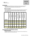
Table 1-1: Sound Examiner SE-400 models explained ............................................................................................................................................. 1
Table 1-2: Keypad keys identified ............................................................................................................................................................................... 2
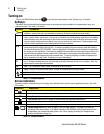
Table 2-1: Softkeys explained..................................................................................................................................................................................... 5
Table 3-1: Meter settings explained ......................................................................................................................................................................... 11