


2-3
Catalyst Switch Module 3110G, 3110X, and 3012 for IBM BladeCenter Hardware Installation Guide
OL-12192-01
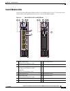
Chapter 2 Switch Module Installation
Preparing for Installation
Installation Guidelines
Note This product is not intended to be connected directly or indirectly by any means whatsoever to interfaces
of public telecommunications networks.
Consider these guidelines before you install the switch module:
• Fill any unoccupied interconnect bays or any unoccupied power module bays in the blade enclosure
with filler modules.
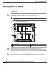
• Identify the bays in which you will insert the switch modules. Plan to install the first switch module
in bay 1, the second in bay 2, and so on up to bay 4, if possible.
See the IBM blade enclosure documentation for more information about the specific enclosure
model, the interconnect bay options, and the port mapping between the blade enclosure and the
switch modules.
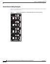
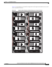
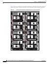
• For switch stacks, you should first install and configure the switch module that will be the stack
master before installing any additional switch modules. See the
“Creating Switch Stacks” section on
page 2-6 for more information.
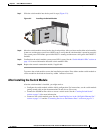
• The orange release latch on the switch module means that it is hot-swappable. To maintain proper
system cooling, you must replace a hot-swap switch module within 1 minute of removal.
• Verify that clearance to the switch-module front panel is such that
–
Front-panel indicators can be easily read.
–
Access to ports is sufficient for unrestricted cabling.
–
The X2-10GB-CX4 transceiver-module minimum-bend radius and connector length is met. See
the X2 transceiver module documentation for more information.
• Confirm that cabling is away from sources of electrical noise, such as radios, power lines, and
fluorescent lighting fixtures. Make sure that the cabling is safely away from other devices that might
damage the cables.
• For copper connections on Ethernet ports, cable lengths from the switch module to connected
devices can be up to 328 feet (100
meters).
• For cable requirements for X2 module connections, see the “Cable and Adapter Specifications”
section on page B-2. Each port must match the wave-length specifications on the other end of the
cable, and the cable must not exceed the required cable length.
• Operating environment is within the ranges listed in Appendix A, “Technical Specifications.”
• Review and become familiar with the safety guidelines in the Regulatory Compliance and Safety
Information for the Cisco Catalyst Switch Module 3110G, 3110X, and 3012 for IBM BladeCenter
on the documentation CD.
• Review and become familiar with the safety guidelines, and the temperature, power, and grounding
requirements specified in the IBM blade enclosure installation and user’s guide.
Box Contents
The box contents are described in the switch module getting started guide. If any item is missing or
damaged, contact your supplier for support.