2-5
Catalyst Switch Module 3110G, 3110X, and 3012 for IBM BladeCenter Hardware Installation Guide
OL-12192-01
Chapter 2 Switch Module Installation
Installing the Switch Module
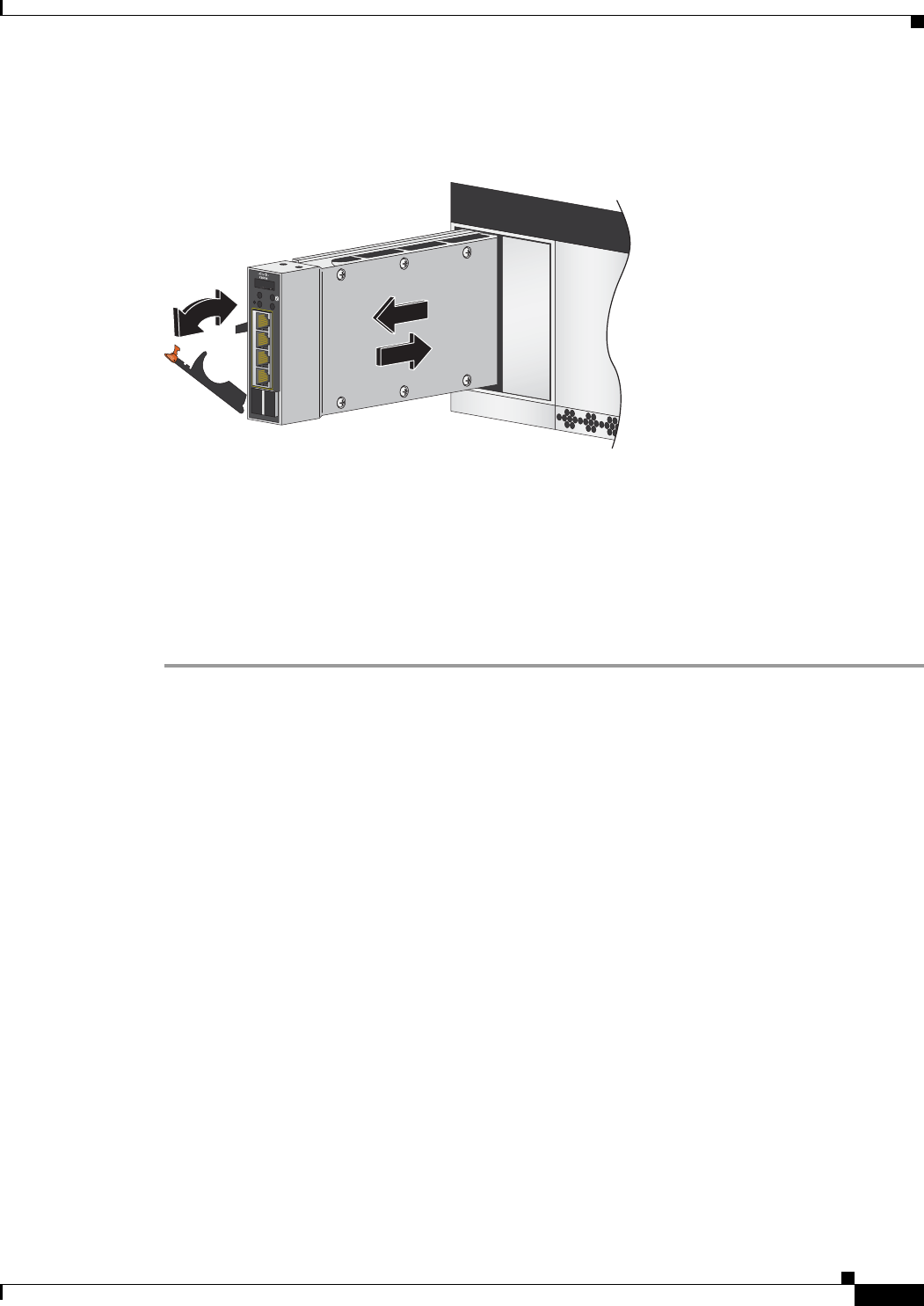
Step 7 Slide the switch module into the bay until it stops (Figure 2-2).
Figure 2-2 Installing the Switch Module
Step 8 Move the switch module release latch to the closed position. After you insert and lock the switch module,
it turns on, and the power-on self-test (POST) runs to verify that the switch module is operating correctly.
The system power LED blinks green while POST is running and then turns solid green when POST is
finished.
Step 9 Confirm that the switch module system power LED is green. See the “Switch Module LEDs” section on
page 1-5 for more information about the switch module LEDs.
Step 10 Replace the acoustic-attenuation module, if applicable.
To remove the switch module, reverse the installation procedure. Place either another switch module or
a filler module in the blade enclosure bay within 1 minute of removal.
After Installing the Switch Module
After the switch module is installed, you might need to:
• Configure the switch module with the initial configuration. For instructions, see the switch module
getting started guide on the documentation CD and also on Cisco.com.
• Connect the StackWise Plus cables to create a switch stack. See the “Creating Switch Stacks”
section on page 2-6 for more information.
• Connect to the switch-module ports. See the “Installing Devices in the 10-Gigabit Ethernet Slot”
section on page 2-11 and the “Connecting Devices to the Ethernet Ports” section on page 2-13.
C
O
N
S
O
L
E
M
O
D
E
M
B
R
M
S
T
LNK
!
ACT
15
LNK
ACT
16
LNK
ACT
17
LNK
1
STACK
2
ACT
18


