


2-13
Catalyst Switch Module 3110G, 3110X, and 3012 for IBM BladeCenter Hardware Installation Guide
OL-12192-01
Chapter 2 Switch Module Installation
Connecting Devices to the Ethernet Ports
Connecting Devices to the Ethernet Ports
The 10/100/1000 Ethernet ports use standard RJ-45 connectors with Ethernet pinouts. The maximum
cable length is 328 feet (100 meters). The 100BASE-TX and 1000BASE-T traffic requires Category
5,
Category
5e, or Category 6 UTP cable. The 10BASE-T traffic can use Category 3 or Category 4 cable.
Caution Category 5e and Category 6 cables can store high levels of static electricity. Always ground the cables
to a suitable and safe earth ground before connecting them to the switch module or other devices.
The autonegotiation feature is enabled by default on the switch module. At this setting, the
switch-module ports configure themselves to operate at the speed of attached device. If the attached
device does not support autonegotiation, you can explicitly set the switch-module port speed and duplex
parameters. To maximize performance, either let the ports autonegotiate both speed and duplex, or set
the port speed and duplex parameters on both ends of the connection.
For simplified cabling, the automatic medium-dependent interface crossover (auto-MDIX) feature is
enabled by default on the switch module. With auto-MDIX enabled, the switch module detects the
required cable type for copper Ethernet connections and configures the interface accordingly. Therefore,
you can use either a crossover or a straight-through cable for connections to a switch-module
10/100/1000 Ethernet port regardless of the type of device on the other end of the connection.
See the switch module software configuration guide and the command reference on Cisco.com for more
information about enabling or disabling autonegotiation and auto-MDIX.
If auto-MDIX is disabled, use the guidelines in Table 2-1 to select the correct cable for connecting the
switch-module 10/100/1000 Ethernet ports to other devices. See the “Cable and Adapter Specifications”
section on page B-2 for cable-pinout descriptions.
Where to Go Next
If the default configuration is satisfactory, the switch module does not need further configuration. You
can use any of the management options described in the
“Management Options” section on page 1-9 to
change the default configuration.
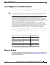
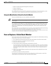
Table 2-1 Recommended Ethernet Cables (When Auto-MDIX is Disabled)
Device Crossover Cable
1
1. 100BASE-TX and 1000BASE-T traffic requires twisted four-pair, Category 5, Category 5e, or
Category 6 cable. 10BASE-T traffic can use Category 3 or Category 4 cable.
Straight-Through Cable
1
Switch module to switch
module
Yes No
Switch module to hub Yes No
Switch module to computer or
server
No Yes
Switch module to router No Yes
Switch module to IP phone No Yes