


1-3
Catalyst Switch Module 3110G, 3110X, and 3012 for IBM BladeCenter Hardware Installation Guide
OL-12192-01
Chapter 1 Product Overview
Hardware Features
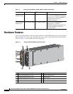
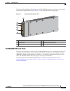
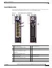
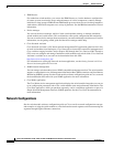
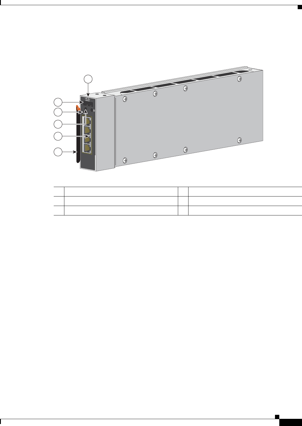
The Catalyst Switch Module 3012 includes the 10/100/1000 Ethernet ports, console port, release latch,
and the switch module LEDs shown in
Figure 1-2 and described on the following pages.
Figure 1-2 Catalyst Switch Module 3012
10/100/1000 Ethernet Ports
The Catalyst Switch Module 3110G and 3012 10/100/1000 Ethernet ports use standard RJ-45 connectors
with Ethernet pinouts. The maximum cable length is 328 feet (100 meters). The 100BASE-TX and
1000BASE-T traffic requires Category
5, Category 5e, or Category 6 unshielded twisted pair (UTP)
cable. The 10BASE-T traffic can use Category 3 or Category 4 UTP cable.
For information about the 10/100/1000 Ethernet port connections and specifications, see the
“Connecting Devices to the Ethernet Ports” section on page 2-13 and Appendix B, “Connector and
Cable Specifications.”
1 Catalyst Switch Module 3012 4 Switch module LEDs
2 Console port 5 10/100/1000 Ethernet ports
3 Mode button 6 Release latch
270430
C
O
N
S
O
L
E
M
O
D
E
LNK
!
ACT
15
LNK
A
CT
16
LN
K
AC
T
17
LNK
ACT
18
1
2
5
6
3
4