


2-7
Catalyst Switch Module 3110G, 3110X, and 3012 for IBM BladeCenter Hardware Installation Guide
OL-12192-01
Chapter 2 Switch Module Installation
Creating Switch Stacks
Connecting a Switch Stack
Follow these steps:
Step 1 Install the member switch modules if you have not already done so.
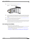
Step 2 Remove the dust covers from the StackWise Plus cables, and store them for future use.
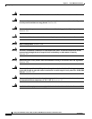
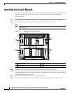
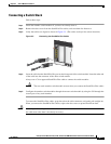
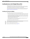
Step 3 Verify that cables are aligned as shown in Figure 2-3. (The cables are keyed for correct insertion.)
Figure 2-3 Connecting the StackWise Plus Cables
Step 4 Insert the cable into the StackWise Plus port on the front panel of the switch module. Insert the other end
of the cable into the connector of the other switch module.
Always use a Cisco-approved StackWise Plus cable to connect the switch modules.
Caution The new stack-member switch module restarts when you connect the StackWise Plus cables.
Step 5 Configure the member switch modules through the master switch module by using the CLI through the
console port of any stack member.
To remove the StackWise Plus cables, grasp the tab on the cable connector, and gently pull straight out.
When you remove the StackWise Plus cables, replace the dust covers to protect them from dust.
Caution Removing and installing the StackWise Plus cable can shorten its useful life. Do not remove and insert
the cable more often than is absolutely necessary.
C
O
N
S
O
L
E
M
O
D
E
M
B
R
M
S
T
LNK
!
ACT
15
LNK
ACT
16
LNK
ACT
17
LNK
1
STACK
2
ACT
18
201898