


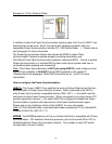
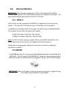

Example of “2-Pair” Ethernet Cable:
In addition to allow the Power Synchronization signal to pass, the Furuno HUB101 has
switches that can be set to “block” this signal thus allowing connection with non-
compatible Power Synchronization devices (PC, FAR-Series Radar …). Please refer to
next paragraph for more information.
The Power Synchronization feature also allows the NN3D’s unique “Data
Synchronization” feature to operate properly providing redundancy and
Point/Route/Track Data Synchronization between networked MFDs. Failure to enable
Power Synchronization in a multiple MFD system could lead to system data loss or
unintentional data updating and overwriting!
Note: If the Power Synchronization is NOT (not using HUB101) used, make sure that
the MFD set as Master is ALWAYS the first MFD powered on the network!!!
(Please refer to the paragraph “Which MFD should be set as ” p.4641 for more
information)
How to configure the Power Synchronization:
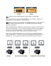
HUB101: The Furuno HUB101 has switches for each individual Ethernet port that can
enable/disable its Power Synchronization function. When connected to an MFD or
other Power Synchronization compatible devices (PSU, DFF1…), the switch must be
configured to allow Power Synchronization. When connected to any other device (PC,
previous generation sensors…) the switch MUST be configured to disable the Power
Synchronization to protect other devices from the Power Synchronization signal.
Please refer to the Installation Guide of the HUB101 for more information.
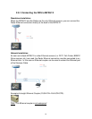
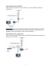
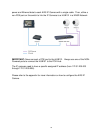
Note: A 2-Pair Ethernet cable is recommended when connecting a PC to a NavNet3D
network (FUSA P/N= 000-167-171).
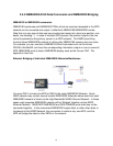
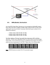
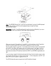
MFDBB: The MFDBB processor unit has an Internal Hub that is compatible with Power
Synchronization. DIP switches inside the processor unit can be turned ON or OFF to
enable/disable the Power Synchronization feature. The number on each DIP switch
corresponds to the port number.
32