


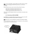
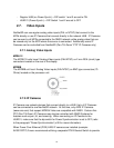

- Regular HUB (no Power Synch.) = DIP switch 1 and 2 are set to ON
- HUB101 (Power Synch.) = DIP Switch 1 and 2 are set to OFF
2.7. Video Inputs
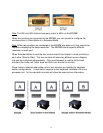
NavNet3D can use regular analog video inputs (PAL or NTSC) that connect to the
MFDs directly or use IP Cameras that connect directly to the network HUB. IP Cameras
can be seen by all MFDs connected to the NN3D network unlike analog video that can
be viewed only on the MFD where the source is connected. Additionally some IP
Cameras can be controlled from NavNet3D (Pan-Tilt–Zoom “PTZ” IP Cameras only)
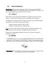
2.7.1. Analog Video Inputs
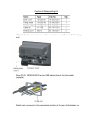
MFD8/12
The MFD8/12 units have 2 Analog Video inputs (PAL/NTSC) on 2 mm RCA (cinch) type
connectors located on the rear of the display
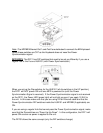
MFDBB
The MFDBB unit has 4 Analog Video inputs (PAL/NTSC) on BNC type connectors (75
Ohms) located on the processor unit
2.7.2. IP Cameras
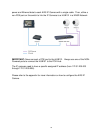
IP Cameras are network devices that connect directly to a HUB. Up to 4 IP Cameras
can be connected to one NavNet3D network. At this time, only AXIS IP Cameras
(www.axis.com) that support MPEG4 Video are compatible with NN3D. Certain Axis
PTZ (Pan-Tilt-Zoom) IP Cameras may also be controlled with NN3D Systems for
features such as pan, tilt, and zooming. When connecting an IP Camera to the
HUB101, make sure that the dip switch for Power Synchronization is set to OFF (refer
to the paragraph “Power Synchronization” p.26 for more information).
When Power Over Ethernet (POE) AXIS IP cameras are installed (example:
AXIS212PTZ) Furuno recommends utilizing a separate POE Ethernet Switch to provide
34