


3. Configuration
3.1. Introduction
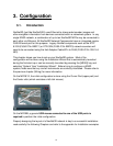
NavNet3D (just like NavNetVX2) uses Ethernet to share radar/sounder images and
other navigation information from devices connected within a networked system. In any
single NN3D network, a combination of up to ten NavNet3D MFDs may be connected to
each other via Ethernet. All NavNet3D Network Components have an integrated regular
RJ45 Ethernet port for this purpose. Legacy NavNet components such as the ETR-
6/10N (FUSA P/N= BBFF1) or ETR-30N (FUSA P/N= BBFF3) network sounders will
need to be connected using the Hub Adapter Cable 6Pin to RJ45 (FUSA P/N= 000-144-
463).
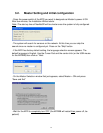
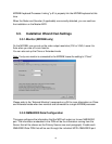
This chapter shows you how to set up your NavNet3D system. Most of the
configuration will be done using the Installation Wizard that is automatically launched
during the first start up or can be manually launched by pressing the [MENU] key and
selecting “System” then “Installation Wizard”. Before trying to configure a NN3D
system, make sure that any and all instruments are correctly interfaced. Please refer to
the previous chapter (Wiring) for more information.
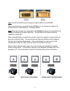
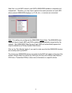
On the MFD8/12, the initial configuration is done using the Cursor Pad (upper pad) and
the Center click (which emulates a left click mouse).
On the MFDBB, a generic USB mouse connected to one of the USB ports is
required to perform the initial configuration.
Properly designing the layout of a NavNet3D network is key to a successful installation:
read carefully the following Chapters and refer to the appendix for Installation examples.
44