


2-1
2. RADAR OPERATION
This chapter covers radar operation, including the ARP (Auto Plotter) function. ARP
requires a Model 18x4C/19x4C series network radar equipped with the ARP circuit board.
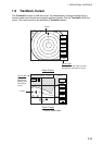
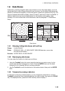
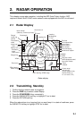
2.1 Radar Display
TRAIL 30m
02m30s
G1 IN
G2 OUT
ES H
EAV L
IR L
EBL1
27.0°R
VRM1
5.666nm
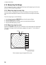
Range/
range ring
interval
Presentation
mode
Zoom area
Zoom
window
Guard zone 1
Trail time
Trail elapsed time
Guard zone 1
Guard zone 2
Echo stretch
Interference rejector
Guard zone 2
VRM2
VRM1
EBL1
Range ring
Pulselength
Heading
M: Magnetic
T: True
Heading line
EBL1 bearing
VRM1 range
Cursor range
and bearing
(Cursor position may
also be shown, in
L/L or Loran C TD.)
EBL2 bearing, VRM2 range
Cursor
Alarm icon
Battery icon
EBL2
327.1°R
VRM2
8.212nm
12/
H-UP
3nm
LP
319. 9
°M
EBL2
Echo averaging
359.9 °R
11.70
nm
+
Own ship vector
(ARP-equipped model,
true vector mode)
North marker
(Head-up, Course-up mode)
S
I
M
Simulation
mode
Radar display
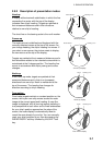
2.2 Transmitting, Stand-by
1. Confirm that the network radar is plugged in.
2. Press the DISP key to select a radar display.
3. Press the POWER/BRILL key momentarily.
4. Press the RADAR STBY soft key to highlight TX on its label.
5. Press the RETURN soft key.
When the radar picture is not required, but you want keep it in a state of readiness, press
the RADAR TX soft key to highlight STBY on its label.