


12
13
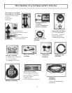
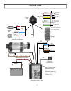
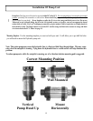
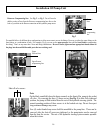
Pump Unit: The Pump unit will need to be mounted within at least 20” of the ECU. It will need to be mounted
in a horizontal position to a solid surface. Do not mount the pump vertical with the pump end down, air gets
trapped in the pump head end and it will not work correctly. Do not lengthen or splice the #5 wire or the orange
and black power wires. See page 18
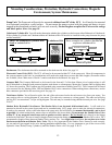
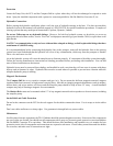
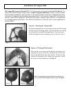
Unbalanced Cylinder Kit: You will need to determine whether the cylinders on the boat are either Balanced or Unbalanced.
If the cylinder or cylinders are Unbalanced then an Unbalanced Kit will need to be installed on the pump between the pump
and the manifold.
Deckmount: The deckmount should be mounted on the dash near the helm. See page 24
.
Electronic Control Unit (ECU): The ECU will need to be mounted within 20” of the pump unit. Most all components in
the system connect to this unit, so considerations will need to be made due to access and cable lengths. (Extension cables
are available.) Note: Make note of Serial #’s and record them in the Manual. See page 18.
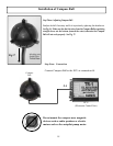
Compass Ball: The Compass Ball needs to be located in the forward 1/2 of the boat. Mount it in a location where it will
not be disturbed or damaged, and protected against wash down or submergence. Mount the Compass Ball no higher than
10’ above the waterline. The Compass may be extended using extensions available from TR-1. The Compass ball will need
to be accessed for the Warning Horn, GPS and Shadow Drive valve connections. When making those connections, use the
blue connectors provided in the accessory pack. See page 19
Tach Sensor Cables: You will need to splice the end of the tach sensor lead to the tach sensor wire from your motor. You
may need to refer to a wiring diagram of your motor. The other wire connects to a clean ground. The other end will plug
into the ECU at connection # 2 as per wiring diagram. The tach may be extended using shielded twisted pair wire. See page
26 & 27.
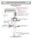
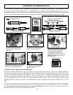
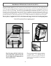
Shadow Drive Hydraulic Valve/Sensor: The Shadow Drive is an electronic bi-directional valve. It will need to be
mounted as shown in the system layout and can be extended using 18-22 gauge wire to make the electrical connections.
It needs to be mounted closer to the helm than to the pump unit, and will need to be mounted horizontally, and as level
as possible. (In a dual station helm, mount closer to and below the lowest helm.) Do not mount the Shadow Drive Valve
within 12” of any magnetic interference such as speakers or drive motors. Do Not Install
valve directly to the ttings
at the back of the helm. Be sure to install a length of hose between the tting at the helm and the Shadow Drive valve. TR-1
recommends a length of hose between Shadow Drive and any Tee. In a single helm installation, do not place a tee in the
line between the helm and Shadow Drive Valve. This is very important for the Shadow Drive feature to work correctly.
Air can and will get trapped in the valve during installation and bleeding. It’s very important to get all the air out of the
Hydraulic Lines, Helms, Pump, Cylinder (s) and The Shadow Drive valve. See page 21 & 22.
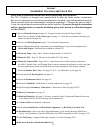
Mounting Considerations, Protection, Hydraulic Connections, Magnetic
Environment, System Maintenance
B
A
L
A
N
C
E
D
C
Y
L
I
N
D
E
R
Unbalanced Cyl.
Unbalanced Cyl.
These examples are cylinders that Do Not
require an unbalanced kit
Unbalanced Cyl.
Unbalanced Cyl.
Unbalanced Cyl.
These are examples of cylinders that
Need an unbalanced kit
Unbalanced Kit
Unbalanced Cyl.
Unbalanced Cyl.