


16
17
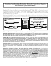
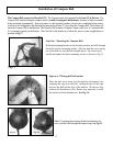
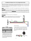
Return or Compensating line: See Fig. 2. or Fig. 3. You will need to
add the section of hose from the Return or compensating hose line on the
back of your helm to the Return connection on the hydraulic pump motor.
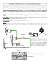
Note:
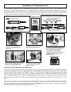
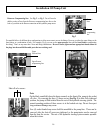
On the black manifold (where the hoses connect) on the front of the pump is also a shut
off valve. By screwing the three (3) brass screws (See Fig 5) to their fully tightened
position, the pump is uid isolated from the rest of the hydraulic steering system. The
normal operating position of these screws is at the backed out stop. Do not force past
stop-permanent damage may occur.
Four (4) socket headed cap screws hold the manifold to the pump face. These can be
removed, after the shut off screws are tightened, so the pump/motor can be removed
from the boat for service. The rest of the hydraulic steering system remains operable
when this is done.
Shut off valve screws
Fig. 5
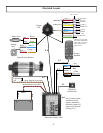
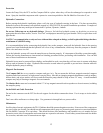
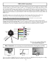
The manifold allows for different hose congurations to allow more room to access the ttings. You may use either the upper ttings or the
front ttings, or a combination of both. For example, (Fig 4) you can use the upper pressure lines and the front Return/ compensating
line tting. Don’t use any more than 3 hose and tting combinations. Be sure to insert, tighten and use appropriate thread sealant on
the plugs into the manifold threaded ports that are not being used.
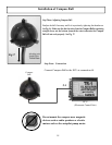
Fig. 3
Upper
Pressure lines
Upper Return/
compensating line
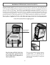
Fig. 2
Return/
compensating
line
Pressure
lines
Fig.4
Example
Installation Of Pump Unit