


8
9
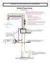
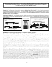
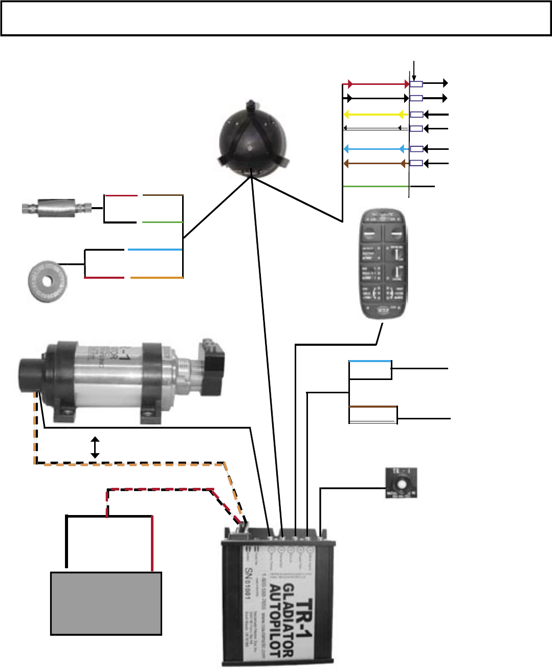
# 3
Remote/
Handheld
Compass
Ball
Shadow Drive
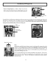
Warning
Horn
Hydraulic Pump & Motor
Deckmount
On/Off Switch
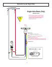
# 2
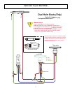
# 1
# 5
# 4
Orange and Black Twisted Wire
Red and Black Twisted Wire
Red ( + )
Black( - ) Blue (- )
Orange ( + )
Red
Black
Brown
Green
Battery
+
-
Port
Engine Tach
STBD
Engine Tach
Blue ( + )
Black ( - )
Brown ( - )
White ( + )
**
**
Note: For diesel engine
installation, use the
engine(s) alternator(s)
tachometry output(s) as
input(s) to the autopilot
See Page 26-27.
Tach Sensor
Do not extend
or splice these
wires
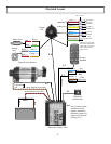
Electrical Layout
Red ( +)
Black (- )
Green (GND)
Yellow ( + )
White ( - )
Blue ( + )
Brown ( - )
NMEA Out
NMEA In # 1
NMEA In # 2
Chart Plotter
Overlay
NMEA IN*
GPS #1
NMEA out*
{
{
{
}
}
}
GPS #2
NMEA
out*
Not normally Used
Wire Connectors
( + )
( + )
( + )
( - )
( - )
( - )
*Refer to your speci c
electronics manual for
color codes or refer to
GPS connections on
pages 39-42.
ECU
(Electronic Control Unit)
Black
Red