


26
27
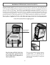
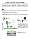
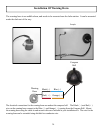
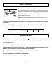
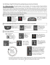
Tach Sensor Cables: The tachometry connection is a very intricate part of the Gladiator and must always be connected. In most
cases this can be simply done behind the dashboard at the tachometer display or just before the display. You must always refer to the
engine’s owner’s manual or shop manual to locate the color codes and location of tachometry wiring. If you have any questions,
please don’t hesitate to call our Tech Support at 1-866-559-0229
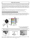
You will need to splice the Positive end (s) of the tach sensor lead (s) to the tach sensor wire from your motor. Negative end (s) connect
to a clean ground. The other end will plug into the ECU at connection # 2.
(You may possibly be able to pull and use a Black (-) wire
from the wiring harness on some Outboards) See wiring diagram on page 7. The wire may be extended using shielded twisted pair
wire.
For Single engines you will use the Blue (+) and the Black (-) wires. The Brown and White wire you will strip and twist together and
terminate with a wire connector.
For Two engines you will use the Blue (+) and the Black (-) on the Port Engine Tach and the Brown (-) and White (+) on the Starboard
engine. For three or more outboards; use the (outside) Port and Starboard engines.
Do not run tachometry wires near high current conductors or electrically noisy device.
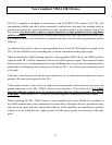
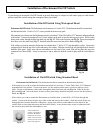
This Chart is a Guide Only and is to help you with your TR-1 Gladiator Tachometer connections and should not be used as factual
information. Please check your specic motors manual for verication of the wire colors to make these connections on your motor.
I/O’s Gasoline
If you know for sure it is an analog tach signal
-Can take from the pulse or signal post off the tach gauge
If you know for sure it is digital tach signal
-Take from the pulse or signal post on the alternator -Use any engine ground OTHER than the alternator ground
If no post on the alternator to get signal from
-Take signal directly off coil, use negative side. -Use any engine ground. -May require an RC lter available from TR-1
Diesel
Connection to a Cummins Diesel 540 may require a “Magnetic Tach Pickup,” Cummins part number 3078155, available for order
from a dealer.
For Yanmar 6 cylinder – Model #6LPAM tach signal can be located in the bell housing. Find the terminals with the Orange and Black
wires. The Orange wire is (+) signal, and the Black wire is (-) ground.
If you know for sure it is an analog tach signal
-Can take from the pulse or signal post off the tach gauge
If digital tach signal
-Take from the pulse or signal post on the alternator- Use any engine ground OTHER than the alternator ground
If no post on the alternator to get signal from - You will have to use the wires from the tooth counter, (this will vary in color per
motor).
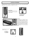
Yamaha Outboards, Except F350 or Outboards using the command link guages.
+ Green (positive)
- Black (negative)
Must be taken from the bullet plug (one will be open on each wire) in the cable bundle approx. 4-6 inches from the tach gauge itself.
For Yamaha F350 and others that use the command link guages:
Use a Digital to Analog converter. Yamaha part number MAR-6X6DA-C0-00. Available from a Yamaha dealer.
Tachometry Connections
continued....