


14
15
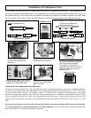
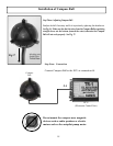
Installation of Unbalanced Valve
B
A
L
A
N
C
E
D
C
Y
L
I
N
D
E
R
Unbalanced Cyl.
Unbalanced Cyl.
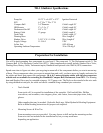
These examples are cylinders that Do Not
require an unbalanced kit
Unbalanced Cyl.
Unbalanced Cyl.
Unbalanced Cyl.
These are examples of cylinders that
Need an unbalanced kit
Unbalanced Kit
Unbalanced Cyl.
Unbalanced Cyl.
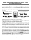
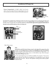
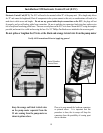
1) Loosen and remove the four
(4) screws on the manifold of the
pump motor.
2) Replace the O-rings in the pump
with the new O-rings in the kit.
3) Place the unbalanced valve between
the pump motor and the manifold with
the O-rings facing the manifold.
Six O-rings are required and are
supplied in the kit. Three (3) are in the
pump motor and three (3) are in the
unbalanced valve.
4) Insert the new longer screws that came
with the kit, lining up the holes in the un-
balanced valve and the pump motor.
5) Tighten all four screws apply
a thread locking compound and
tighten to 35 in lbs.
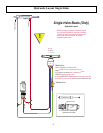
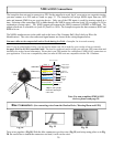
If the system was ordered as an Unbalanced System, the kit is installed at the factory. The unbalanced valve
accessory is a pilot operated bleed valve. It is intended for use when the steering cylinder tted to the vessel is of
the unbalanced type. In use the bleed valve equalizes the amount of hydraulic oil that is returned to the tank from
the low pressure side of the cylinder with the amount of oil that is being pumped to the high pressure side.
O-rings on valve
towards manifold
Manifold
Pump Motor
Un-balanced
Valve
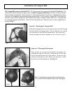
Adjustment Screws
Fig. 1
Unbalanced Valve adjustment and calibration:
To check or reset the setting of the valve. To check the setting, compare the amount of brass screw extending outside the
valve body on both sides of the valve, (See Fig 1) if this is equal and the shoulder of both brass screws is .015”-.020” below
the valve outside surface, then the valve setting is correct. To reset the valve setting, rst fully tighten the screws equal
amounts by turning them clockwise until they stop. The equal amounts can be veried by comparing the amount of brass
screws extending outside the valve body, after tightening they should be equal. If they are not equal, unscrew one and
tighten the other one until they are equal. After establishing the equal center position, then unscrew each screw by 2 1/2 full
turns.
Do not unscrew the brass screws more than the specied amount as permanent damage will be caused to the housing.
Also do not operate the system with the brass screws fully tightened as this will cause ow restrictions and therefore
draw more electrical current and may damage components.