


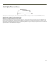
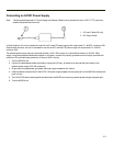
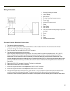

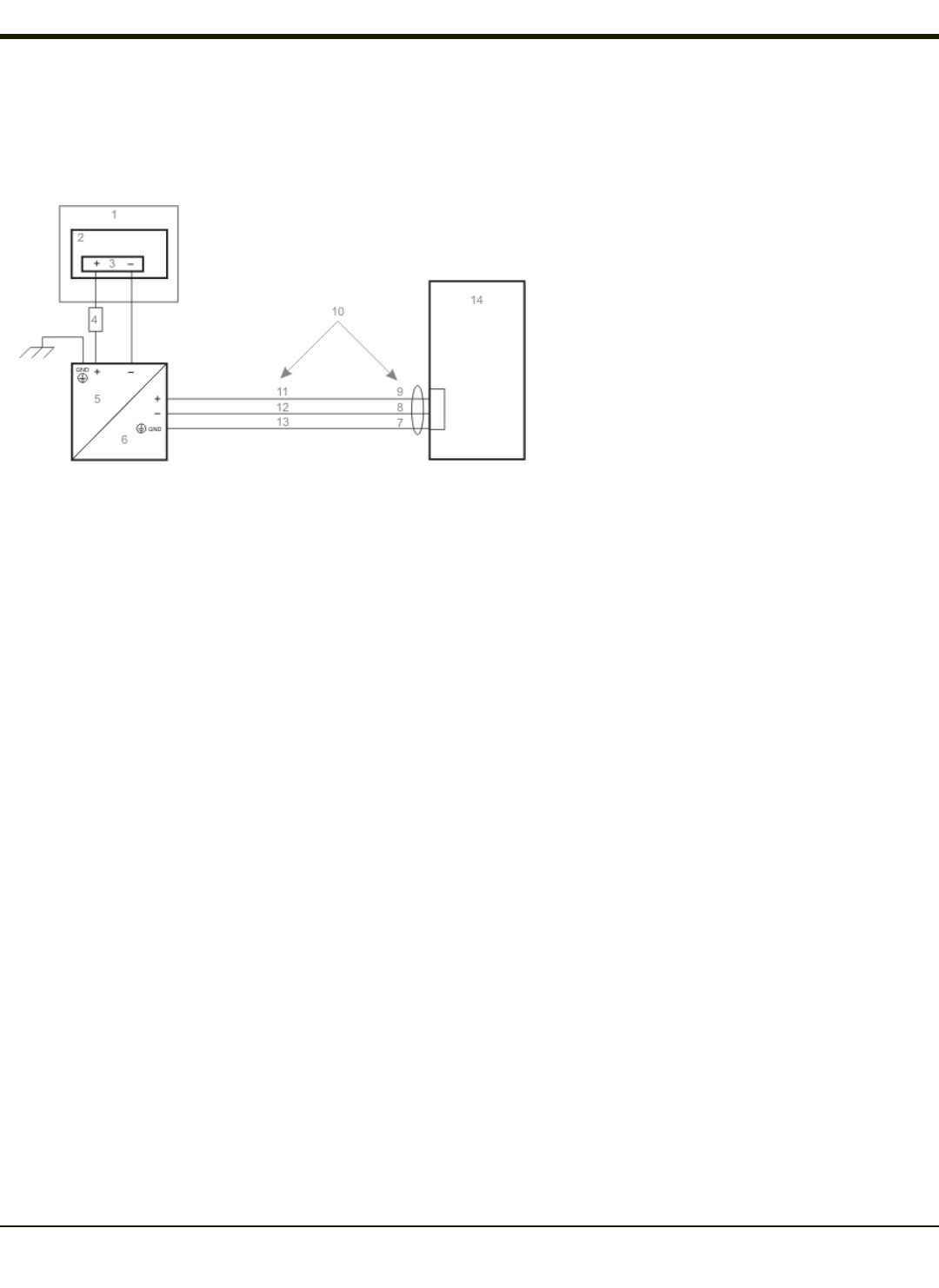
Wiring Schematic
1. Existing Circuitry on Vehicle
2. Forklift Battery
3. Main Switch
4. 5A slow fuse close to power source
5. Power input
6. Isolated DC power output
7. Green
8. Red / Black
9. Red / White
10. Use color scheme corresponding to input wire
provided
11. Brown
12. Blue
13. Green
14. Vehicle mounted cradle
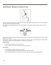
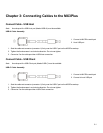
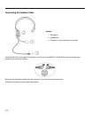
Connect Vehicle Electrical Connection
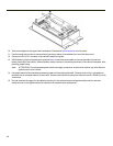
1. The vehicle cradle must be empty.
2. Begin by connecting the power cable to the MX3Plus's vehicle cradle. Work from this connection with the last
connection being to the vehicle’s power source.
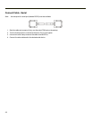
3. Route the cable from the cradle to the DC to DC converter.
4. Cut the cable to length and strip the wire ends.
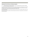
Route the power cable the shortest way possible. The cable is rated for a maximum temperature of 105°C (221°F).
When routing this cable it should be protected from physical damage and from surfaces that might exceed this
temperature. Do not expose the cable to chemicals or oil that may cause the wiring insulation to deteriorate. If the
vehicle is equipped with a panel containing Silicon Controller Rectifiers (SCR’s), avoid routing the power cable in close
proximity to these devices.Always route the cable so that it does not interfere with safe operation and maintenance of
the vehicle.
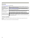
5. Remove the DC to DC converter lid screws. Put them in a safe place.
6. Remove the lid from the DC to DC converter.
7. Attach the stripped wire ends to the output side of the DC to DC converter.
8. Attach the stripped wire ends to the input side of the DC to DC converter.
9. The input and output blocks each have two + plus and two – minus connectors. Either connector in the block can be
used to connect the matching polarity wire. The input and output blocks also each have two chassis ground
connections. When connecting the MX3Plus cradle to vehicle power, use one chassis ground connector in each block.
3-5