


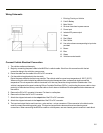
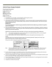


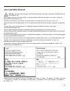

Vehicle Power Supply Footprint
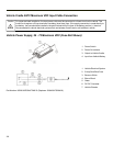
Power Supply Dimensions
Length: 9.25” / 23.5 cm
Height: 2.5” / 6 cm
Width: 4.7” / 12 cm
Mounting hole center
Width: 3.5” / 9 cm
Length: 8.75” / 22.2 cm
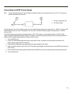
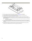
1. If the MX3Plus is in the cradle, it can be either On or Off during this process.
2. Turn the Power Supply toggle switch to the Off position.
3. While observing the fuse requirements specified above, connect the power cable as close as possible to the actual
battery terminals of the vehicle. When available, always connect to un-switched terminals in the vehicle fuse panel,
after providing proper fusing.
IMPORTANT:
For uninterrupted power, electrical supply connections should not be made at any point after the ignition
switch of the vehicle.
4. Route the cable the shortest way possible. The input cable from the connection to the battery is rated for a maximum
temperature of 60°C (140°F). When routing this cable it should be protected from physical damage and from surfaces
which might exceed this temperature.
Additionally do not expose the cable to chemicals or oil that may cause the wiring insulation to deteriorate.
Note: If the vehicle is equipped with a panel containing Silicon Controlled Rectifiers (SCR's), avoid routing the
power cable in close proximity to these devices.
Always route the cable so that it does not interfere with the driver's safe operation and maintenance of the
vehicle.
Use proper electrical and mechanical fastening means for terminating the cable. Properly sized "crimp" type
electrical terminals are an accepted method of termination.
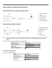
Wiring color codes for Honeywell supplied DC input power cabling:
Vehicle Supply Wire Color
+24-72 Max VDC (DC +) Brown or White
Return (DC -) Blue or Black
Vehicle Chassis (GND) Green
Note: The input power cord for the DC-DC Power Supply uses white, black and green wires. Some Honeywell
products have DC input power cords with brown, blue and green wires. The previous table shows the
correct electrical connection for either type of cable.
5. Provide mechanical support for the cable by securing it to the vehicle structure at approximately one foot intervals,
taking care not to over tighten and pinch conductors or penetrate outer cable jacket.
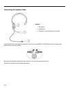
6. Connect the Power Supply to the cradle by aligning the keyed water tight connector pins to the power connector; push
down on the keyed water tight connector and twist it to fasten securely.
7. Turn the Power Supply on. The ON LED on the Power Supply illuminates when it is receiving power from the vehicle.
8. The Cradle Status LED illuminates green.
9. The MX3Plus CHGR LED illuminates.
3-9